
This process intensification technique involves changing a tower’s internals and operating mode and the separate movement of the liquid and vapor phases. This can significantly increase column throughput and reduce energy requirements, while improving separation performance.
Process intensification (PI) is a set of innovative principles for enhancing the driving forces and synergistic effects in a process to obtain: dramatic reductions in the size of a plant needed to achieve a production objective; significant increases in the production capacity within a given equipment volume; a step reduction in energy usage per ton of product; or a marked cut in the formation of wastes and/or byproducts (1). The main principles of PI are (2):
- maximize the effectiveness of intra- and inter-molecular events
- give each molecule the same processing experience
- optimize the driving forces at every scale and maximize the specific surface area to which these forces apply
- maximize the synergistic effects of partial processes.
PI encompasses recognized technologies in reactor engineering (e.g., microreactors, spinning-disk reactors), heat exchange (e.g., compact heat exchangers), mixing (e.g., static mixers), and distillation (e.g., dividing-wall columns, reactive distillation), among others (3, 4). Particularly in distillation systems, PI has received much attention, with the aim of increasing both energy and separation efficiency. Various techniques have been reported (5).
A dividing-wall column (DWC) is a practical implementation of a Petlyuk configuration for multicomponent distillation (in which one condenser and one reboiler of a two-column sequence are replaced by thermal coupling of the prefractionator with the main column). A DWC allows further equipment integration and cost savings by combining the functions of the two distillation columns of a Petlyuk configuration into a single shell. DWC technology offers major benefits over classical distillation design: high thermodynamic efficiency due to reduced remixing effects; 25–40% lower energy requirements; high purities for all product streams; lower maintenance costs; 40% smaller footprint and 20% less piping; and up to 30% lower investment costs due to the reduced number of equipment units (6–8).
The heat-integrated distillation column (HIDiC) is the most radical of the distillation PI approaches. A heat-pump-assisted distillation column makes efficient use of internal heat integration: The rectifying section of the column operates at a higher pressure and serves as the heat source, while the stripping section of the column acts as a heat sink. Remarkably, HIDiC can achieve energy savings of up to 70% compared to conventional distillation columns (9).
High-gravity (HiGee) distillation, a variation of the rotating packed bed (RPB) concept, employs a rotating torus-shaped rigid bed to achieve a high gravity field 100–1,000 g). The higher heat- and mass-transfer coefficients and higher flooding limits allow the use of high-surface-area packing. Reported benefits include height equivalent to a theoretical plate (HETP) values as low as 1–2 cm, as well as throughput about 3–6 times higher and equipment volumes 2–3 orders of magnitude lower than conventional packed columns (10).
Reactive distillation (RD) carries out reaction and distillation in the same piece of equipment: As the reactants are converted to products, the products are simultaneously separated and the unused reactants are internally recycled. RD setups may consist of multiple catalyst systems, gas and liquid traffic over the catalyst, separation, mass flow, and enthalpy exchange — all optimally integrated in a single processing unit. As a proven technology, RD has been applied industrially to equilibrium-limited reactions (e.g., synthesis of methyl tert-butyl ether [MTBE], tert-amyl methyl ether [TAME], and acetates), with demonstrated benefits that include better conversion and selectivity, less waste and byproducts, and typically more than 40–50% savings in capital and operating costs (5).
All of these distillation techniques employ the conventional continuous countercurrent contact of the vapor and liquid phases flowing simultaneously through the column. This article gives an overview of an alternative operating mode — known as cyclic distillation — based on separate phase movement. It explains the principle of operation, design and control methods, and main benefits and limitations, and it discusses some industrial applications. Cyclic distillation can be rather easily implemented in existing columns by simply changing the internals and the operating mode, thus bringing new life to old towers.
The evolution of cyclic distillation technology
References to periodic (cyclic) operation of distillation columns go back to the early 1960s, when M. R. Cannon introduced the idea of cyclic operation in distillation, liquid-liquid extraction, and particle separation (11). Cycling operation can be implemented in several ways.

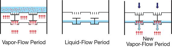
▲Figure 1. Cyclic distillation works by alternating a vapor-flow period (a) with a liquid flow-period (b) and then repeating with another vapor-flow period (c). The darkening color from the bottom to the top indicates the liquid-phase concentration gradient across the plates of the column. Source: Adapted from (12).
The simplest method is controlled cycling (Figure 1), which involves alternating between a vapor-flow period, when the thrust of the rising vapor prevents liquid downflow, and a liquid-flow period, when the liquid flows down the column, moving from each tray to the tray below (12). This type of operation requires no downcomers, so the plates are simpler, cheaper, and more flexible. A timer controls the opening and closing of the valve in the vapor line connecting the reboiler to the distillation tower. Separate phase movement and lack of mixing between the liquid from different trays (which have different compositions) improve distillation performance.
Several researchers successfully tested this mode of operation experimentally in columns equipped with conventional internals for several separations, such as:
- benzene/toluene, using brass and mesh-screen plates (13)
- methyl-cyclohexane/n-heptane, using packed-plates (14)
- acetone/water, using sieve trays (15)
- methanol/water, using conventional stages (16, 17).
These early results demonstrated important advantages of the cyclic operation mode — capacity and tray efficiency higher than conventional distillation. This allowed higher feed rates to be processed and enabled the required separation to be achieved using lower energy input (with the same number of trays) or fewer trays (at the same energy input).
The experimental results also proved the limitations of the cyclic operation mode. In particular, the separate movement of the liquid and vapor phases becomes difficult with higher numbers of trays. At the time, it appeared there was “hardly any hope that distillation towers with much more than 10 trays [could] be operated effectively in the cycling mode” (18). Several solutions to the problem of the incomplete separation between the liquid and vapor flows were suggested, such as the use of external manifolds to equalize the pressure between trays at the beginning of each liquid-flow period (19) and trays with inclined surfaces that introduced time delays in liquid flow (20).
▲Figure 2. Trays designed for cyclic distillation feature valves and a sluice chamber below the tray. During vapor flow, the valves are closed and the liquid remains on the tray. During liquid flow, the valves open and the liquid flows from the tray to the chamber below. When the next vapor-flow period begins, the sluice chamber opens and the liquid flows to the empty tray below. Source: Adapted from (22).
A real breakthrough, however, was achieved only recently, when a new type of tray designed specifically for cyclic operation was invented (21). These trays (Figure 2) have valves and sluice chambers located under the trays (22). During the vapor-flow period, the valves are closed and the liquid stays on the tray. During the liquid-flow period, the valves open and the liquid flows from the tray to the sluice chamber below. When another vapor-flow period begins, the sluice chamber opens and the liquid flows to the empty tray below. This type of tray eliminates the complications related to the larger number of trays.
The early simulation and design models of cyclic distillation were developed at a time when the available computing power was low and expensive. Consequently, the accuracy of the results was limited. The models considered only binary mixtures and employed drastic simplifying assumptions, such as linear equilibrium, infinite reboiler, and negligible condenser holdup (16, 17, 19, 23, 24). Later studies (12, 21, 22) relaxed those assumptions and provided more realistic models. In addition, noniterative design algorithms were recently suggested and applied for mixtures with general nonlinear vapor-liquid equilibrium (VLE) (12, 22, 25).
These developments — the availability of reliable design and control methods, increased computing power, and the introduction of specialized hardware that allows separate phase movement — have spurred renewed interest in cyclic distillation.
Principle of operation
Cyclic operation can be achieved by controlled cycling, stepwise periodic operation, a combination of these two methods, or stage switching.
Controlled cycling (described earlier) is the preferred scheme, because it is the simplest from both the construction and the operating points of view. The equipment is the same as in conventional distillation (shell, trays, condenser, and reboiler), and the length of each period can be easily regulated by a cycle timer and one automatic valve in the vapor line between the reboiler and the distillation tower (or in the direct steam-injection line).
Stepwise periodic operation uses trays fitted with an inlet and an outlet that are normally opened and closed by on-off valves, and a side reservoir large enough to contain one tray’s holdup. The trays have no downcomers, but they can be completely emptied through their outlet directly into the reboiler. During the vapor-flow period, the condensate is sequentially collected in the reservoirs. At the end of the vapor-flow period, the bottom product is removed from the reboiler, the content of all trays is moved to the reboiler, and the content of the reservoirs is transferred to the corresponding tray. Then, a new cycle begins. Stepwise periodic operation directly manipulates the liquid flow, thereby circumventing the hydrodynamic problems that occurred in early columns operated in the controlled-cycling mode.
Stage switching employs several vapor nozzle stages, a reboiler, and a condenser that are connected by a complicated pipeline network and on-off valves. A cyclic change in the network structure is achieved by opening and closing relevant valves. The placement of the stages relative to each other is not important, as long as they are above the reboiler and below the condenser — which could improve the flexibility of the system at the expense of complexity and need for thermal insulation.
The remainder of the article focuses on controlled cycling with simultaneous tray draining, since this operating mode was proven to be feasible in an industrial environment.
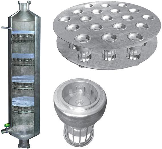
◀Figure 3. Trays designed for cyclic distillation have no downcomers. Instead, valves and sluice chambers effect liquid flow. Photo courtesy of MaletaCD.
From the outside, a cyclic distillation column looks like a typical tower in a chemical plant. However, the cross-sectional view of the inside of a cyclic distillation column (Figure 3) reveals the absence of downcomers and the presence of different internals that allow for efficient, separate phase movement.
The operating cycle of a cyclic distillation column with simultaneous tray draining consists of two segments:
- a vapor-flow period, during which vapor flows upward through the column and liquid descends from the sluice chambers to the tray beneath
- a liquid-flow period, during which vapor flow is stopped, reflux and feed liquid are supplied to the column, and liquid travels downward from each tray to the sluice chamber below.
If the vapor velocity exceeds the weeping limit, the liquid does not overflow from tray to tray during the vapor-flow period (Figure 1a). When the vapor supply is interrupted, the liquid drops by gravity to the sluice chamber (Figure 1b). When the vapor supply is started again, the sluice chambers open, and the liquid is transferred by gravity to the tray below (Figure 1c).
Cyclic distillation is analogous to conventional distillation with liquid-phase concentration gradients across the plates of the column (26). In the case of cyclic distillation, time is the independent variable, whereas in conventional distillation, the independent variable is distance. The concept of cyclic distillation could be extended to catalytic cyclic distillation, a novel setup that combines the benefits of reactive distillation with those of a cyclic operating mode (22).
Simulation and design models
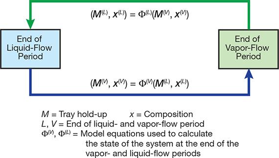
▲Figure 4. The cyclic distillation simulation model solves the mass and energy balance equations iteratively.
For the vapor-flow period, the model uses the usual mass and energy balance equations for each tray, but they are written in the dynamic form and without the terms that represent liquid flowing in and out. For the liquid-flow period, the model simply describes the movement of the liquid from one tray to the tray below, taking into account the mixing that occurs on the feed tray and the reboiler. The model solves the vapor and liquid equations in an iterative procedure (Figure 4).
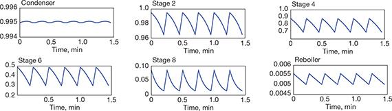
▲Figure 5. This trend chart records the change in liquid composition (y-axis) in the condenser, reboiler, and four trays over several operating cycles. (Note that the scales are different.) Source: Adapted from (12).
The results can be represented as the change in various operating parameters (e.g., temperature, pressure, flowrate, composition) on each tray over time. Figure 5 illustrates the change in the liquid composition in the condenser, reboiler, and selected trays over several operation cycles (12). The sustained oscillations reveal that the distillation column works in a cyclic operation mode.

▲Figure 6. The liquid-phase composition changes as the liquid moves down the column. Source: Adapted from (12).
Figure 6 provides an alternative representation — the composition of the liquid as it flows down the column. This is the basis of a design method (12, 25) that involves writing a mathematical model in the form of delay-differential equations that describe the change of the liquid state as it moves backward in time, from reboiler to condenser, while in contact with the vapor rising from the tray below. The time needed for the vapor to travel up the column from the reboiler to the condenser determines the total number of trays.
Illustrating the benefits and limitations
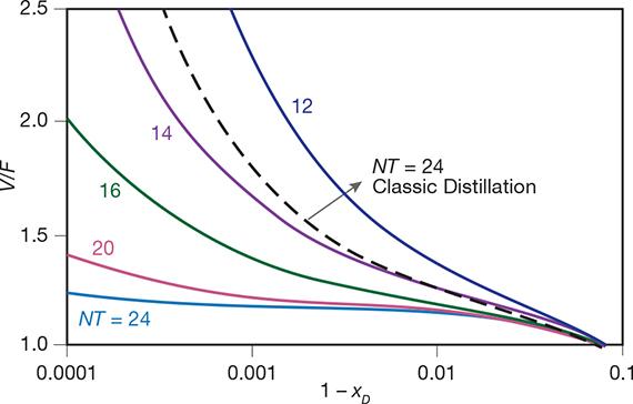
▲Figure 7. The energy requirements (expressed as V/F) are much lower, and the separation performance (expressed as 1–xD) is much higher, for cyclic operation than for conventional distillation. Source: Adapted from (12).
Consider the separation of a classic model mixture: an equimolar mixture of benzene and toluene. Figure 7 plots the energy requirements, expressed as vapor to feed ratio (V/F), as a function of the separation performance, expressed as product purity (xD), in a conventional distillation column with 24 trays and in cyclic distillation using 24, 20, 16, 14, and 12 trays (12). The energy requirements (which are directly proportional to the vapor flowrate, V), as well as the number of trays (NT) required to obtain a given purity at a given vapor flowrate, are significantly lower for cyclic distillation than for conventional distillation. Thus, for a fixed number of trays, cyclic distillation has lower energy requirements (lower operating cost) and achieves higher purities (better separation performance). Alternatively, for the same vapor flowrate, fewer trays (lower investment cost) are required for cyclic distillation.
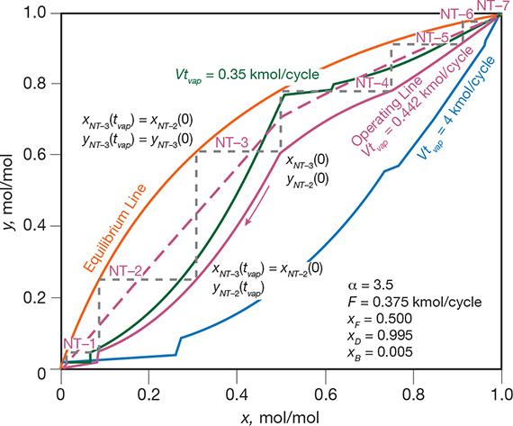
▲Figure 8. The cyclic operating mode can be represented using equilibrium (orange) and operating (magenta, blue, green) lines. The dashed magenta line is for classic distillation and the solid magenta line is for cyclic distillation, both at Vtvap = 0.444 kmol/cycle. The blue and green lines are for the limiting cases of cyclic distillation: blue for the minimum vapor flowrate and infinite number of trays (Vtvap = 0.35 kmol/cycle), green for the minimum number of trays and infinite vapor flowrate (Vtvap = 4 kmol/cycle). Source: Adapted from (12).
A plot similar to a McCabe-Thiele diagram provides insight into the cyclic distillation operations. For example, Figure 8 represents the distillation of an ideal binary mixture with a relative volatility of α = 3.5 (a common value), at various operating conditions. It is worth noting the existence of a minimum vapor flowrate (Vmin) that corresponds to an infinite number of trays, and a minimum number of trays (NTmin) that corresponds to an infinite vapor flowrate (12). These limiting cases are represented by the blue and green operating lines drawn at Vtvap = 0.35 and 4 kmol/cycle, respectively. At the same vapor flowrate, cyclic distillation (magenta operating line drawn at Vtvap = 0.442 kmol/cycle) achieves the same product purities using fewer stages than conventional distillation (dashed magenta operating line).
Even though it may seem more complicated, the periodic operation mode does not add control difficulties in practice. As in conventional distillation, the amount of distillate and bottoms withdrawn from the column regulate the levels in the reflux drum and reboiler. For quality control, one can measure temperatures in the stripping and rectifying sections at certain moments in time, for example, at the end of the vapor-flow period. Then, by means of a suitable discrete-time control algorithm, the rate of vapor flow or the duration of the next vapor-flow period is adjusted. In this way, feed rate and composition disturbances are effectively rejected (12).
Note, however, that cyclic operation also has its limitations. The application of cyclic operation to vacuum distillation seems rather difficult, and the performance enhancement critically depends on the complete separation between the liquid- and vapor-flow periods. The sluice-chamber trays discussed here seem to avoid the limitations of simple trays in vacuum applications (27).
Industrial applications
Cyclic distillation has been carried out at pilot scale for the separation of benzene/toluene, methanol/water, acetone/water, and methyl-cyclohexane/n-heptane mixtures. At production scale, cyclic distillation is already used in the petrochemicals industry for kerosene fractionation.
It is also being used in the food industry, where a cyclic distillation column acts mainly as a stripper that concentrates alcohol from about 8 wt% ethanol to 27–45 wt% ethanol. In the beer manufacturing process, the ethanol-water mixture leaving the fermenter contains approximately 30 impurities accounting for less than 0.2 mol% of the stream. This stream, which has an alcohol concentration of 10 vol% (3.29 mol%), enters the top tray of the cyclic distillation column (stripping column), while steam is injected into the reboiler. The specification for the ethanol concentration in the top distillate varies between 13 mol% and 24 mol%, and typically has a value of about 18.25 mol%, while the concentration of ethanol in the bottoms must not exceed 0.004 mol% (21).
Over the past decade, MaletaCD has built and installed several commercial-scale distillation columns ranging in size from 0.4 m to 1.7 m and equipped with five to 42 trays. One column for ethanol concentration has 15 stages, a 0.5-m dia., and a 20-m3/day capacity. The first dividing-wall column to employ cyclic operation is a 42-tray, 1.5/1.7-m-dia., 25-m3/hr unit that processes kerosene and mineral spirits at a plant in the Middle East.
Reference 27 provides more details about a pilot-scale cyclic distillation column operated in industry, including a comparison to an existing column.
Other potential applications for cyclic distillation include: biofuels (bioethanol, biodiesel, biobutanol) production, organic chemical synthesis, specialty chemical manufacturing, pharmaceutical production, gas processing, and petrochemical manufacturing. Major manufacturers of distillation equipment should be able to develop and deliver the required internals for the revamping of existing (tray) towers into cyclic distillation columns.
When planning and executing such a revamp project, keep in mind the tips Bouck offered for avoiding revamping pitfalls (28):
- perform an objective economic reality check
- consider long-term capacity needs
- plan for personnel changes
- provide the right input to process simulation
- interpret the simulation results correctly
- consider heat-transfer capabilities and hydraulic capacity
- identify existing equipment limitations
- know the design capabilities of the vendor and contractor
- use special expertise for design reviews
- pay attention to installation details.
As the industrial application of cyclic distillation becomes more widespread, users and equipment providers will continue to gain valuable knowledge regarding the technology in general, as well as best practices and lessons learned.
Closing thoughts
With a change of internals and operating mode, cyclic distillation can give new life to old distillation columns — increasing column throughput, reducing energy requirements, and improving separation performance. So, it might seem surprising that industry has not widely adopted cyclic distillation.
This is not the first time that the chemical industry is reluctant to implement novel process intensification technologies. Dividing-wall column technology faced a similar situation. From about the mid-1980s to 2000, only one industrial company was using DWCs, although it did operate many units around the world. Various perceived issues — such as complex internals, control difficulties, and the lack of design and control methods — made other companies reluctant to invest in the technology. Nevertheless, DWC technology flourished and today is considered proven technology, with a large number of industrial implementations in place and sufficient design and operating information available.
Cyclic distillation shows similar promise. To reach its potential, research needs to address several challenges:
- proving the advantages in new industrial applications that involve difficult separations, e.g., close-boiling components, high-purity products, significantly larger column capacities
- developing process control techniques to address any tight purity requirements or feed variability (there is already much knowledge about distillation control that can be used for this work)
- further developing and implementing shortcut and rigorous design and simulation methods (for use in process simulators) that incorporate hydrodynamic models, for example, by making use of today’s computing power and recent advances in computational fluid dynamics (CFD)
- developing improved tray designs that allow a perfect separation of phase movements, and expanding the worldwide availability of that equipment from a larger number of equipment manufacturers.
ANTON ALEXANDRU (TONY) KISS is a senior project manager at AkzoNobel — Supply Chain, Research & Development (Zutphenseweg 10, 7418 AJ Deventer, the Netherlands; Phone: +31-26-366-9420; Email: tony.kiss@akzonobel.com; Website: www.tonykiss.com), where he serves as an expert in separation technologies, reactive-separation processes, process intensification, and integrated sustainable processes, as well as process modeling and simulation of industrial processes. He is also a professor of separation technology at the Univ. of Twente in the Netherlands. He has published several textbooks, book chapters, patents, and more than 100 scientific articles. For his pioneering work and career achievements, he received in 2013 the Hoogewerff Jongerenprijs and the AkzoNobel Innovation Excellence Award. Kiss holds a PhD in chemistry and chemical engineering from the Univ. of Amsterdam, and MS and BS degrees in chemical engineering from Babes-Bolyai Univ. of Cluj-Napoca in Romania, and he was a post-doctoral research fellow at Delft Univ. of Technology (TU Delft) and the Univ. of Amsterdam. He is a member of AIChE, IChemE, Society of Chemical Industry (SCI), European Society of Mathematical Chemistry (ESMC), European Federation of Chemical Engineering (EFCE), and the EFCE Working Party on Computer Aided Process Engineering (CAPE-WP).
COSTIN SORIN B ÎLDEA is a professor at the Univ. Politehnica of Bucharest (Dept. of Chemical and Biochemical Engineering, Polizu 1-7, 011061 Bucharest, Romania; Phone: +40-21-402-3903; Email: s_bildea@upb.ro) and a visiting professor at Nazarbayev Univ., Astana (Kazakhstan), where he teaches process design and process control courses. Previously, he was an assistant professor at Delft Univ. of Technology and researcher at the Univ. of Amsterdam. A specialist in the field of nonlinear dynamics and in integration of process design and process control, he has published more than 100 scientific papers and is the coauthor of two books. In 2011, he received the Nicolae Teclu prize of the Romanian Academy for his publications in the field of design, control, and automation in process engineering. He holds a PhD from the Univ. of Amsterdam and two MSc degrees in chemical engineering and industrial process control from Univ. Politehnica of Bucharest, and is a member of the Romanian Society of Chemical Engineering (SICR) and Society of Chemistry Industry (SCI).
Literature Cited
- Stankiewicz, A., and J. A. Moulijn, “Process Intensification: Transforming Chemical Engineering,” Chemical Engineering Progress,96 (2), pp. 22–34 (Jan. 2000).
- van Gerven, T., and A. Stankiewicz, “Structure, Energy, Synergy, Time — The Fundamentals of Process Intensification,” Industrial and Engineering Chemistry Research,48 (5), pp. 2465–2474 (Mar. 2009).
- Tsouris, C., and J. V. Porcelli, “Process Intensification: Has Its Time Finally Come?” Chemical Engineering Progress,99 (10), pp. 50–55 (Oct. 2003).
- Doble, M., “Green Reactors,” Chemical Engineering Progress,104 (8), pp. 33–42 (Aug. 2008).
- Kiss, A. A., “Advanced Distillation Technologies — Design, Control, and Applications,” John Wiley and Sons, Hoboken, NJ (2013).
- Shah, P., “Squeeze More Out of Complex Columns,” Chemical Engineering Progress,98 (7), pp. 46–55 (July 2002).
- Schultz, M. A.,et al., “Reduce Costs with Dividing-Wall Columns,” Chemical Engineering Progress,98 (5), pp. 64–71 (May 2002).
- Parkinson, G., “Dividing-Wall Columns Find Greater Appeal,” Chemical Engineering Progress,103 (5), pp. 8–17 (May 2007).
- Kiss, A. A., and Z. Olujic, “A Review on Process Intensification in Internally Heat-Integrated Distillation Columns,” Chemical Engineering and Processing,86, pp. 125–144 (Dec. 2014).
- Kiss, A. A., “Distillation Technology — Still Young and Full of Breakthrough Opportunities,” Journal of Chemical Technology and Biotechnology, 89 (4), pp. 479–498 (Apr. 2014).
- Cannon, M. R., “Controlled Cycling Improves Various Processes,” Industrial and Engineering Chemistry,53 (8), p. 629 (Aug. 1961).
- Patrut, C.,et al., “Cyclic Distillation — Design, Control and Applications,” Separation and Purification Technology,125, pp. 326–336 (Apr. 2014).
- Gaska, R. A., and M. R. Cannon, “Controlled Cycling Distillation in Sieve and Screen Plate Towers,” Industrial and Engineering Chemistry,53 (8), pp. 630–631 (Aug. 1961).
- McWhirter, J. R., and M. R. Cannon, “Controlled Cycling Distillation in a Packed-Plate Column,” Industrial and Engineering Chemistry,53 (8), pp. 632–634 (Aug. 1961).
- Schrodt, V. N.,et al., “Plant-Scale Study of Controlled Cyclic Distillation,” Chemical Engineering Science,22 (5), pp. 759–767 (May 1967).
- Matsubara, M.,et al., “Binary Periodic Distillation Scheme with Enhanced Energy Conservation I — Principle and Computer Simulation,” Chemical Engineering Science,40 (5), pp. 715–721 (1985).
- Matsubara, M.,et al., “Binary Periodic Distillation Scheme With Enhanced Energy Conservation II — Experiment,” Chemical Engineering Science,40 (5), pp. 755–758 (1985).
- Larsen, J., and M. Kümmel, “Hydrodynamic Model for Controlled Cycling in Tray Columns,” Chemical Engineering Science,34 (4), pp. 455–462 (1979).
- Furzer, I. A., “Mass Transfer in a Periodically Cycled Plate Column Fitted with a Manifold,” Chemical Engineering Science,35 (6), pp. 1299–1305 (1980).
- Szonyi, L., and I. A. Furzer, “Periodic Cycling of Distillation Columns Using a New Tray Design,” AIChE Journal,31 (10), pp. 1707–1713 (Oct. 1985).
- Maleta, V. N.,et al., “Understanding Process Intensification in Cyclic Distillation Systems,” Chemical Engineering and Processing,50 (7), pp. 655–664 (July 2011).
- Patrut, C.,et al., “Catalytic Cyclic Distillation — A Novel Process Intensification Approach in Reactive Separations,” Chemical Engineering and Processing,81, pp. 1–12 (July 2014).
- Rivas, O. R., “An Analytical Solution of Cyclic Mass Transfer Operation,” Industrial and Engineering Chemistry,16 (3), pp. 400–405 (July 1977).
- Duffy, G. J., and I. A. Furzer, “Periodic Cycling of Plate Columns: Analytical Solution,” Chemical Engineering Science,33 (7), pp. 897–904 (1978).
- Toftegard, B., and S. B. Jorgensen, “Design Algorithm For Periodic Cycled Binary Distillation Columns,” Industrial and Engineering Chemistry Research,26 (5), pp. 1041–1043 (May 1987).
- Sommerfeld, J. T.,et al., “Studies of Controlled Cyclic Distillation: I. Computer Simulations and the Analogy with Conventional Operation,” Separation Science and Technology,1 (2–3), pp. 245–279 (1966).
- Maleta, B. V.,et al., “Pilot-Scale Studies of Process Intensification by Cyclic Distillation,” AIChE Journal,61 (8), pp. 2581–2591 (Aug. 2015).
- Bouck, D., “Ten Distillation Revamp Pitfalls to Avoid,” Chemical Engineering Progress,110 (2), pp. 31–38 (Feb. 2014).
1

Copyright Permissions
Would you like to reuse content from CEP Magazine? It’s easy to request permission to reuse content. Simply click here to connect instantly to licensing services, where you can choose from a list of options regarding how you would like to reuse the desired content and complete the transaction.