
Hydrofoil impellers are typically associated with turbulent-flow mixing. Simple calculations, computational fluid dynamics, mixing software, and laboratory testing reveal that they are also effective in laminar-flow applications.
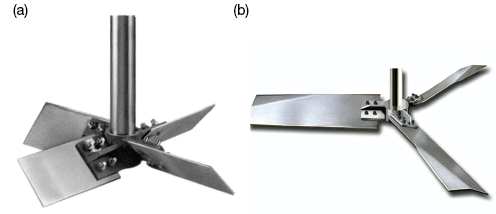
▲Figure 1. (a) Pitched-blade turbine impellers typically have four blades and are used to mix low- and medium-viscosity fluids. (b) Hydrofoil blades have an aerodynamic shape that requires less torque than pitched blades.
The selection of an agitator impeller for mixing fluids in tanks is a widely researched field, with many resources available to study fluid flow. Conventional wisdom holds that medium-viscosity fluids in transitional flow are best mixed with a pitched-blade turbine (Figure 1a) and low-viscosity fluids in turbulent flow are mixed best with a hydrofoil impeller (Figure 1b). (High-viscosity fluids in a laminar regime are best mixed with a close-clearance impeller such as a helical ribbon, which is not discussed in this article.)
Pitched-blade turbines typically have four blades at an angle of 45 deg. and have been used since at least the 1940s for general-purpose mixing of low- and medium-viscosity fluids, as well as for simple blending and solids suspension. They can create a vortex at the liquid surface to incorporate dry solids or gases. Their simple shape makes them economical to manufacture.
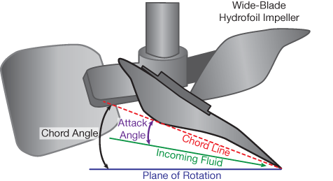
▲Figure 2. On a hydrofoil impeller, the camber, angle of attack, and chord angle can be designed and optimized for the fluid and mixing conditions.
Hydrofoil impellers have been used since the 1970s in many mixing applications. They usually have three blades, a low angle of attack (15–25 deg. at the blade tip, to avoid boundary layer separation), and a camber in the blade that causes the chord angle to increase from tip to hub (Figure 2). They have been used to blend low-viscosity liquids in shear-sensitive applications and to suspend solids. The aerodynamic shape makes the blades more effective at producing flow for a given power and speed than pitched-blades and requires less torque for the same mixing conditions.
Although hydrofoil impellers are usually used in turbulent flow and pitched-blade turbine impellers in transitional flow, both have use in some laminar-flow applications. This article compares the performance of pitched-blade turbines and hydrofoils in four ways: manual calculations, computational fluid dynamics (CFD), mixing software, and real-world laboratory testing of a fluid that is very difficult to mix — a high-solids biomass slurry. The analyses demonstrate the utility of hydrofoils in laminar-flow applications and show that they perform better in laminar-flow than pitched-blade turbines. Advantages of hydrofoils include higher pumping for a given power and shaft speed, as well as a more axial flow pattern and better control of shear-thinning fluids.
Impeller performance
Impeller performance characteristics are generally determined empirically by correlating measured data as a function of dimensionless numbers. The four main dimensionless numbers used to study mixing are based on seven key variables: the power delivered (P); the fluid’s density (ρ); the shaft speed (N); the impeller diameter (D); the impeller pumping rate (Q); the fluid’s viscosity (µ); and the tank diameter (T). These variables form the dimensionless numbers:
- power number, NP = P/ρN3D5
- pumping number, NQ = Q/ND3
- Reynolds number, NRe = D2Nρ/µ
- the ratio of impeller diameter to tank diameter, D/T.

Figure 3 presents generic curves for these dimensionless numbers. Flow is fully laminar at Reynolds numbers less than 10, though anything below 40 can be considered laminar flow for most practical purposes. Note that D/T has an effect on both power number and pumping number in turbulent flow, but no effect in laminar flow. Also note that power number is constant in turbulent flow (Reynolds number above 10,000), and becomes inversely proportional to Reynolds number in laminar flow. The dimensionless laminar power number constant, KL, is defined as:
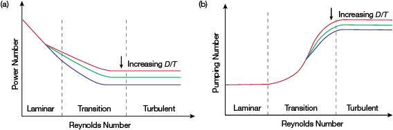
▲Figure 3. (a) A generic power number curve shows that the power number is constant in turbulent flow. (b) A generic pumping number curve shows that the pumping number is constant in both the laminar and turbulent flow regimes and that it is independent of D/T in the laminar region.
Similarly, the pumping number is constant in turbulent flow. It drops as the flow goes through the transition regime, and then becomes constant in laminar flow.
Compare pumping rates by manual calculation
An effective way to study the mixing performance of different impellers is to calculate the power drawn by each impeller under the same conditions. The power number (NP) and the laminar power number constant (KL) act as a foundation to calculate the power. The literature gives values for KL of 27.4 for a typical hydrofoil and 43.2 for a pitched-blade turbine (1). The pumping number (NQ) is used to calculate impeller pumping; the published value of NQ is 0.214 for hydrofoils and 0.2954 for pitched-blade turbines operating in laminar flow (2). With these data, the relative pumping for both impellers operating at the same power input can now be calculated.
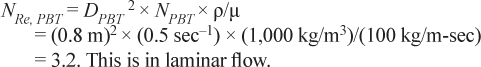
In this example, the tank has a diameter of 2 m, and the fluid has a density of 1,000 kg/m3 and a viscosity of 100 kg/m-sec (100,000 cP). The diameter of the pitched-blade turbine (DPBT) is 0.8 m and the shaft speed is 0.5 sec–1.
To compare the mixing effectiveness of a pitched-blade and a hydrofoil impeller, first calculate the power draw and pumping provided by the 0.8-m-dia. pitched-blade turbine. Then perform iterative calculations to determine the diameter of a hydrofoil impeller that would draw the same power.
For the pitched-blade turbine impeller:
Reynolds number:
Power number:

Power draw:

Impeller pumping:

The 0.8-m-dia. pitched-blade turbine impeller drawing 533 W provides a pumping rate of QPBT = 0.0756 m3/sec.
Now determine the diameter of a hydrofoil impeller that would draw the same power at the same shaft speed. Assume a diameter, calculate Reynolds number, then power number, then power; repeat with different diameters until the power for the hydrofoil matches...
Would you like to access the complete CEP Article?
No problem. You just have to complete the following steps.
You have completed 0 of 2 steps.
-
Log in
You must be logged in to view this content. Log in now.
-
AIChE Membership
You must be an AIChE member to view this article. Join now.
Copyright Permissions
Would you like to reuse content from CEP Magazine? It’s easy to request permission to reuse content. Simply click here to connect instantly to licensing services, where you can choose from a list of options regarding how you would like to reuse the desired content and complete the transaction.