
* This article is based on a paper presented at the 2016 AIChE Spring Meeting and 12th Global Congress on Process Safety, Houston, TX, Apr. 10–13, 2016.
Safety risks and economic costs make shutting down a process when a pressure relief device needs to be isolated or removed less than ideal. Several alternative methods are available that will enable you to isolate these devices while continuing to run your process.
Pressurized equipment must be outfitted with pressure relief devices to protect the equipment from overpressure. These devices — mechanical or instrumented, passive or active — automatically relieve material and energy in response to an increase in system pressure. Pressure relief devices typically refer to pressure relief valves and bursting discs, although explosion hatches, water seals, buckling pin devices, and pressure/vacuum breather valves can also provide overpressure protection.
It is sometimes necessary to isolate and remove pressure relief devices for inspection, maintenance, or repair, and it would be advantageous to have a means to do so without shutting down the process, especially in light of the additional risks associated with shutdown and startup.
This article offers guidance on methods to isolate pressure relief devices while the process continues to operate, and recommends actions that provide temporary overpressure protection.
Pressure relief device isolation
Companies have taken different approaches when isolating and removing pressure relief devices. As a minimum, the ASME Boiler and Pressure Vessel Code requires procedures to ensure that an authorized person continuously monitors the pressure conditions of a vessel when the relief device is isolated and the process is still running (1). Several factors make this a suboptimal approach, including the elevated risk to personnel and the speed at which overpressure may occur relative to response time.
In some cases, safety, practicality, and/or economics justify the installation of a completely independent spare pressure relief device that can provide sufficient relief capacity and serve as an alternative means of overpressure protection. Procedures should be in place to ensure that only one pressure relief device is active at a time and that the switchover between the two pressure relief devices does not leave the pressurized system unprotected for any duration beyond that required to turn the valves. Specialized valves for common inlet lines can be used to reduce the duration of nonprotection while also minimizing inlet line pressure losses (2).
Several alternative approaches to these current practices can be used independently or in concert to ensure that the at-risk pressurized system is adequately protected for the duration of the override:
- temporarily eliminating root causes of potential overpressure events
- temporarily creating alternative pathways that provide overpressure protection
- temporarily modifying the process operation
- temporarily ensuring equivalent or better risk reduction.
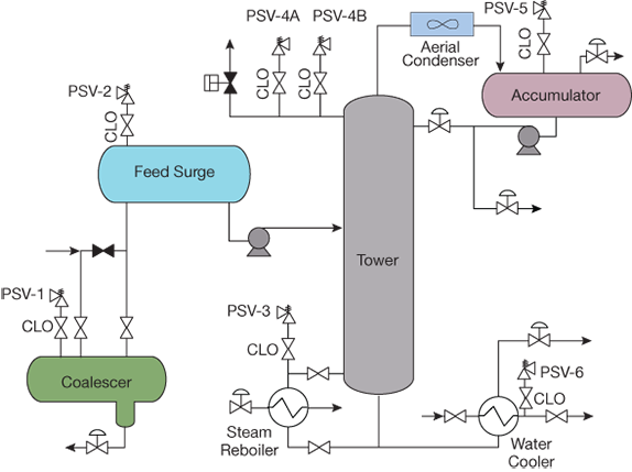
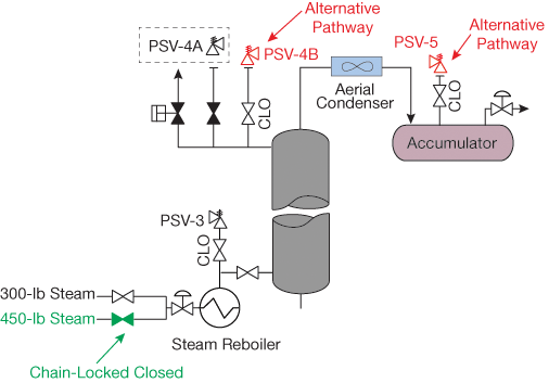
▲Figure 1. A simple distillation process is equipped with several chain-locked open (CLO) pressure safety valves (PSVs), each of which can be isolated using the methods discussed in this article.
These approaches are illustrated with the simple distillation process depicted in Figure 1, which has a feed coalescer to remove water from the feed and a surge drum to provide a steady supply of liquid feed. The reboiler can use either 300-lb or 450-lb steam, and a rundown cooler is employed to cool the bottoms stream. The process includes several pressure safety valves (PSVs), each of which can be isolated by one or more of the alternative methods highlighted in this article.
Eliminate overpressure
Evaluate possible causes of overpressure that could affect the pressurized system being protected by the relief device to be isolated. Identify the root cause of each potential overpressure event, and determine whether that root cause can be temporarily eliminated while the device is isolated. Several techniques can be used to prevent overpressure.
Loss of utility. The loss of a utility (e.g., electricity, cooling water, steam) can affect more than one piece of equipment. Provide an alternative or backup utility source, such as an uninterruptible power supply (UPS) or instrument air bottles.
Manualvalve operation. If the root cause of overpressure involves the operation (opening or closing) of a specific valve, provide a mechanical locking mechanism and/or implement administrative controls to prevent the opening or closing of that valve.
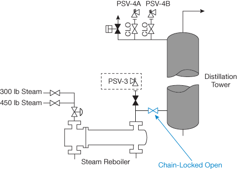
▲Figure 2. Mechanical locking and administrative controls can be used when isolating PSV-3. The isolation valve between the reboiler and distillation tower is chain-locked open (blue) and administrative controls ensure that someone does not close the valve. This creates an alternative path to PSV-4A and PSV-4B, which protect the shellside of the reboiler.
Both mechanical locking and administrative controls are used to safely isolate PSV-3 (Figure 2), which provides overpressure protection for the shellside of the reboiler, for example, in the event of an external fire or if the tubes rupture when the boiler is operating with 450-lb steam service. The isolation valve between the reboiler and distillation tower is chain-locked open (blue) and procedures are instituted to ensure that someone does not close the valve. These actions temporarily eliminate the potential for overpressure caused by an isolated liquid with heat input and create an alternative path (as discussed later).
Reference 1 provides information on mechanical locking elements and administrative controls, as well as additional information on valve failure and valve operation controls. To prevent the inadvertent opening of a valve that normally isolates a higher-pressure source, completely disconnect the source of pressure.
Automatic control valve failure. If the failure of an automatic control valve is the root cause of overpressure, temporarily restrict movement of the actuator to prevent the valve from fully opening or closing. Consult the control valve’s manufacturer for the appropriate mechanical stop mechanism. Restricting the actuator is considered mechanical locking.
Expansion. Heating an isolated fluid can increase the pressure within the vessel or piping containing the fluid. To eliminate thermal or hydraulic expansion, prevent the fluid from being isolated (e.g., use a mechanical locking mechanism to prevent the piping isolation valves from closing) or prevent the addition of heat to the isolated fluid.
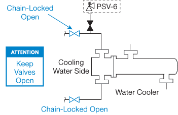
▲Figure 3. When isolating PSV-6, thermal expansion can be temporarily eliminated as a root cause of overpressure by employing mechanical locking mechanisms (blue) to keep the valves on the cooling side of the heat exchanger open and posting signs at these isolation valves.
In the distillation process, PSV-6 provides overpressure protection for the tubeside of the cooler from over-pressure due to thermal expansion. If the cooling tubes become blocked, heat from the shellside of the exchanger can cause the liquid in the tubes to heat up and expand. When isolating PSV-6 (Figure 3), thermal expansion can be eliminated as a root cause of overpressure by employing mechanical locking mechanisms (blue) to keep the valves on the cooling side of the heat exchanger open and posting signs at these isolation valves.
For a thermal-relief valve in nonhazardous service, operating procedures that ensure drainage and proper isolation often provide adequate risk mitigation for the isolation of the pressure relief device.
For a thermal-relief valve in hazardous service, additional measures may be required:
- install mechanical locking elements on the piping isolation valves to prevent the valves from being closed without authorization, thereby preventing the liquid-filled piping from being isolated
- place a conspicuous placard at the location of the isolation valve warning that the valve is not to be closed.
For situations involving hydraulic expansion, prevent the system from being full of liquid when it is isolated by creating a gas pocket that the liquid can expand into, such as with a hydraulic accumulator.
While the temporary elimination of the root cause of overpressure is ideal, it is often impractical, particularly for systems that may be affected by multiple causes of overpressure.
Provide an alternative overpressure protection pathway
Creating a pathway to an alternative means of overpressure protection can be suitable, and more practical, for isolating a pressure relief device without shutting down the process. The ASME Boiler and Pressure Vessel Code, Section VIII NMA M considers this an acceptable practice.
A piping and instrumentation diagram (P&ID) is a useful tool for identifying alternative paths. It is, of course, permissible to have more than one alternative path for different causes of overpressure. In general, the acceptable path(s) with the lowest pressure drops should be used.
Keep in mind the following guidelines on using an alternative overpressure protection pathway.
For each applicable cause of overpressure, identify the source of overpressure and any pressure relief device between the source of overpressure and the system of interest. If a pressure relief device can be found along this path, then that relief device is preferred, provided it meets the sizing and installation criteria. Pressure relief devices that are upstream of the system of interest and upstream of the pressure-generating source are not preferred alternatives, but may be justified based on a detailed analysis.
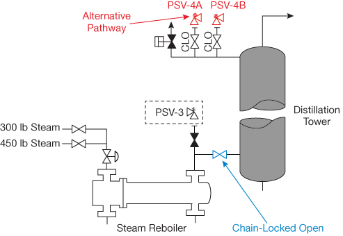
▲Figure 4. When isolating PSV-3, an alternative pathway (red) can be created by chain-locking open the valve between the reboiler and the distillation tower. PSV-4A and PSV-4B provide the alternative pressure relief protection.
When isolating PSV-3, an alternative pathway (Figure 4, red) is created by chain-locking open the valve between the reboiler and the distillation tower. The alternative relief protection in this pathway is provided by PSV-4A and PSV-4B.
If the system has multiple relief devices, as this distillation process does, only one pressure relief device in that installation should be isolated at a time. Credit may be taken for the operation of the pressure relief devices that remain online.
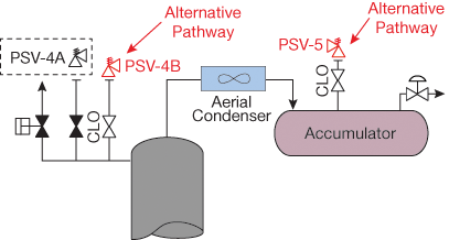
▲Figure 5. When isolating PSV-4A, an alternative pathway (red) that uses PSV-4B and PSV-5 as overpressure protection is adequate when the reboiler is operating with 300-lb steam.
PSV-4A and PSV-4B — which provide overpressure protection for the distillation tower in the event of an external fire, loss of cooling, and boilup, or if the reboiler tubes rupture when operating with 450-lb steam service — cannot both be taken out of service at the same time. When isolating PSV-4A (Figure 5), a possible alternative pathway could be created that uses PSV-4B and PSV-5 as overpressure protection. When the reboiler is operating with 300-lb steam, PSV-4B and PSV-5 together (red) provide adequate pressure-relief capacity; therefore, no further evaluation is required. When the reboiler is operating with 450-lb steam, the combined capacity of PSV-4B and PSV-5 is not sufficient, and other measures are required, as discussed later.
The alternative pathway should not contain any means of automatic isolation. If a means of automatic isolation does exist and the alternative path is the only practical solution, further risk assessment may be needed. Mechanical locking elements and administrative controls may prevent the automatic isolation from occurring for the limited duration of the isolation event. Block valves in the path may warrant mechanical locking elements and administrative controls to prevent unacceptable operation.
Pressure relief devices providing overpressure protection for pressurized equipment downstream of the system of interest should handle only the same fluid phase that normally travels in the alternative path. In the event a different fluid phase is present, further analysis should be performed to ensure the different fluid phase will not adversely affect the pressurized systems or compromise the overpressure protection.
The pressure relief device in the alternative pathway should be sized for the cause of overpressure to ensure adequate capacity in the event overpressure does occur. In many cases, the cause of overpressure for the at-risk pressurized system may coincide with a cause of overpressure for the alternative pressurized system. An engineering evaluation should be performed to determine the appropriate cumulative relief rate required for these cases.
If the alternative pressure relief system is providing overpressure protection for a vessel with a maximum allowable working pressure (MAWP) that is lower than the MAWP of the at-risk pressurized system, the capacity of the alternative pressure relief device should be calculated based on the MAWP of the weaker system.
Pressure relief devices providing the alternative protection should meet the following installation requirements:
- the set pressure of the relief device should be less than or equal to the limiting MAWP of the pressurized system
- the cross-sectional area available for flow within the alternative path should be greater than or equal to the crosssectional area of the inlet to the pressure relief device(s) providing overpressure protection
- the pressure drop between the at-risk pressurized system and the alternative pressure relief device should not adversely affect the overpressure protection
- if the alternative pressure relief device is a pressure relief valve, the pressure drop at the inlet of the alternative pressure relief valve should satisfy limits given in API Standard 520 Part II.
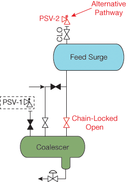
▲Figure 6. PSV-2 can provide overpressure protection for both the feed surge drum and the coalescer when PSV-1 is taken out of service. This alternative pathway (red) is created by chain-locking open the valve between the feed surge drum and the coalescer.
These requirements must be met when isolating PSV-1 (Figure 6), which provides overpressure protection for the coalescer in the event of an external fire or a blocked outlet. PSV-2 can provide overpressure protection for both the feed surge drum and the coalescer when PSV-1 is taken out of service. The alternative pathway (red) is created by chain-locking open the valve between the feed surge drum and the coalescer.
Once the alternative relief devices have been identified, each device should be evaluated to determine whether it can provide adequate capacity and satisfy the installation requirements. Review the inspection reports for the alternative relief device(s) to ensure that the maintenance on the device(s) is current. Finally, document the evaluation and any actions required to ensure the alternative overpressure protection path(s) are established correctly and operated safely.
Modify the process
An additional means of providing adequate overpressure protection is to modify the process operation, often with the goal of reducing relief requirements to match available capacity or installation requirements while the pressure relief valve of interest is out of service. A detailed review of the input parameters for a given overpressure scenario can often identify leverage points.
If the pressure-relief requirement of a system depends on flowrate, the throughput of the process can be reduced to lower the relief requirement of that system. The process turndown, effects on operation, and effects on downstream operations must be considered when contemplating the feasibility of operating at reduced flowrates.
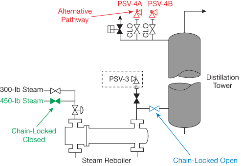
▲Figure 7. When PSV-3 is isolated, PSV-4A and PSV-4B provide adequate overpressure protection when the reboiler is operating with 300-lb steam, but this arrangement is not sufficient when the reboiler is operating with 450-lb steam. Therefore, the process is modified. The isolation valve from the 450-lb steam line is chain-locked closed (green) and the reboiler is operated with 300-lb steam for the short period of time needed to isolate PSV-3.
The best way to protect the distillation process from overpressure while isolating PSV-3 is to modify the process (Figure 7). When the reboiler is operating with 300-lb steam, chain-locking open the valve between the reboiler and the distillation tower allows adequate overpressure protection in the event of a fire. However, the reliability of this action was called into question when the reboiler operates with 450-lb steam. Additional risk reduction measures were deemed necessary, so the process was modified so the reboiler operated with 300-lb steam for the short period of time needed to isolate PSV-3. To ensure this operational change, the isolation valve from the 450-lb steam service line was chain-locked closed (green).
If the relief capacity is set by the maximum discharge pressure produced by rotating equipment, the suction pressure of the rotating equipment can be reduced to lower its discharge pressure. Before implementing this fix, consider the effects it will have on operating equipment, e.g., the minimum net positive suction head.
When the relief requirements of a system are based on the potential for an external fire on wetted vessels, the level of liquid in that vessel can be lowered to reduce the wetted surface area and thus the effective heat input to the vessel. However, the less liquid inventory in a vessel, the sooner the liquid is completely vaporized, creating a vapor-filled vessel that can experience high wall temperatures. Before implementing this fix, consider over-temperature concerns in addition to the effects on operation.
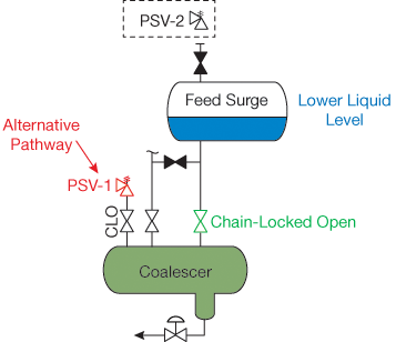
▲Figure 8. To use PSV-1 as alternative overpressure protection during the isolation of PSV-2, the process needed to be modified. The high liquid level (blue) was lowered, which temporarily reduced the maximum vapor generated enough to allow PSV-1 to provide adequate pressure relief capacity. To ensure an open path between the feed surge drum and PSV-1, the block valve between the coalescer and the feed surge is chain-locked open (green).
To isolate PSV-2 (Figure 8), which provides overpressure protection for the feed surge drum in the event of an external fire or overfilling, an alternative pathway that uses PSV-1 for overpressure protection for both the coalescer and the feed surge drum was identified. But, that pathway was marginally inadequate. Therefore, the process was modified to lower the high liquid level (blue), which temporarily reduced the maximum vapor generated enough to allow PSV-1 to provide adequate relief capacity. To ensure an open path between the feed surge drum and PSV-1, the block valve between the coalescer and the feed surge is chain-locked open (green).
When relief requirements are based on heat input, the flowrate of the heating medium can be reduced to obtain a corresponding reduction in heat input. Note that this requires the heat transfer to be dependent on the flowrate (rather than on surface area).
Consider again the isolation of PSV-4A (Figure 5, p. 29). An alternative pathway to overprotection is sufficient while operating with 300-lb steam. When the reboiler is operating with 450-lb steam, however, the combined capacity of PSV-4B and PSV-5 is not sufficient to protect the system if the cooling system fails or if boilup occurs. The process can be modified to reduce the pressure relief requirement so that PSV-4B and PSV-5 would provide adequate pressure relief protection (Figure 9). The reboiler is operated with 300-lb steam for the short period of time needed to isolate PSV-4A, ensuring this by chain-locking closed the isolation valve (green) from the 450-lb steam service line and reducing the feed flowrate.
▲Figure 9. The process is modified to reduce the pressure relief requirement so that PSV-4B and PSV-5 can provide adequate pressure relief protection when PSV-4A is out of service. The feed flowrate is reduced and the reboiler is operated with 300-lb steam for the short period of time needed to isolate PSV-4A; this is ensured by chain-locking closed the isolation valve from the 450-lb steam line (green).
For scenarios involving inadvertent valve opening or control valve failure, the upstream pressure can be reduced and the maximum opening of the valve can be limited to reduce flow through the valve.
The process modification tactic is often used in conjunction with an alternative pathway, particularly when the capacity of the alternative relief device is the limiting factor.
Equivalent risk reduction
Another method of temporary overpressure protection is to provide a means of equivalent risk reduction. This approach is not codified in current recognized and generally accepted good engineering practices (RAGAGEP), but it is a logical extension of overpressure protection by system design and other risk-based efforts, and it is alluded to in API Standard 521 (3). The equivalent risk reduction approach involves demonstrating that other layers of protection can provide the same level of overpressure protection as the pressure relief device being temporarily isolated and taken out of service. To determine this equivalent protection, first assess the risks associated with the isolation of the pressure relief device. A layer of protection analysis (LOPA) (4) can be an appropriate means of assessing these risks.
To take credit for isolation and/or depressuring systems as equivalent risk reduction for a short time frame, those systems should have appropriate means of activation and should be inspected to ensure they work as intended. To evaluate the protection credit of isolation systems, the isolation valves should have tight-shutoff capability. For a depressuring system to receive protection credit, the depressuring valve’s capacity should exceed the required relief rates of the process.
Documentation
Regardless of the approach taken, the analysis, results, and procedure for isolation of a pressure relief device need to be documented. Companies often have a set of safeguard override procedures and documentation that may be appropriate for the isolation of a pressure relief device, as it is a critical piece of the engineering controls at the facility. This documentation should include:
- the actions required to mitigate the risks associated with the isolation of a pressure relief device
- a summary of each applicable cause of overpressure and the means by which the cause is mitigated
- P&ID(s) that identify the elements of the piping systems that require some action while the device is isolated.
For risk mitigation provided by means of alternative overpressure protection paths, these additional items should be included in the documentation:
- P&ID(s) that indicate the alternative path(s)
- calculations that demonstrate the alternative pressure relief device(s) are capable of providing adequate over-pressure protection.
For risk mitigation as identified by means of risk assessment, an additional item should be included:
- risk assessment report that indicates the risk mitigation measures found to be appropriate.
Final thoughts
When pressure relief devices require isolation and removal for inspection or repair during operation, it is possible to perform an engineering assessment to identify a means for providing temporary overpressure protection. Regardless of the approaches taken, the time during which the relief device is isolated should be minimized, reinforcing the need for planning and preparation for effective and efficient control of this non-routine work process.
Literature Cited
- American Society of Mechanical Engineers, “2010 Section VIII — Nonmandatory Appendix M — Installation and Operation,” in “ASME Boiler and Pressure Vessel Code, 2011a Addendum,” ASME, New York, NY, pp. 660–665 (July 2011).
- DeMichael, D. B., and M. F. Edwards, “Properly Isolate Pressure Relief Devices,” Chemical Engineering Progress, 95 (11), pp. 57–64 (Nov. 1999).
- American Petroleum Institute, “Pressure-Relieving and Depressuring Systems,” API Standard 521, 6th edition, API, Washington D.C., p. 60 (Jan. 2014).
- Center for Chemical Process Safety, “Layer of Protection Analysis — Simplified Process Risk Assessment,” CCPS, New York, NY (Oct. 2001).
1

Copyright Permissions
Would you like to reuse content from CEP Magazine? It’s easy to request permission to reuse content. Simply click here to connect instantly to licensing services, where you can choose from a list of options regarding how you would like to reuse the desired content and complete the transaction.