
This article is based on a paper presented at the 2016 Industrial Energy Technology Conference (IETC), May 2016. The online version of the article includes animated figures courtesy of TLV Corp.
Condensate return systems can have a big impact on productivity, energy efficiency, and site reliability. Use this guide to better understand your condensate return, optimize its operation, and mitigate common pitfalls such as high backpressure and water hammer.
To improve steam system efficiency and reliability, engineers often focus primarily on the steam supply side, addressing problems such as piping leaks, steam trap leaks, and insulation. The conversation rarely shifts to improvement opportunities in the condensate return system, unless significant issues already exist — such as high backpressure, or knocking and the pipe damage it can cause. Plant personnel are typically most concerned with steam supply and the heat that it provides to the manufacturing units, but a condensate return system can have significant impact on production, efficiency, and reliability.
If you are maintaining a sports car, you may be concerned with the fuel quality, injection method, and ignition, but the car will not function well if the exhaust system is compromised or subpar. Exhausted fuel must discharge freely in order for the car to operate effectively. Steam equipment has the same requirement — it must be able to discharge condensate freely.
Although many experienced engineers know a substantial amount about handling steam, there appears to be less understanding of condensate systems, their design, and the many factors that affect their performance. This article discusses those influences, and describes the causes of detrimental effects and possible responses to achieve more-reliable performance. It also gives readers insight into these common questions:
- What causes water hammer in condensate systems? How can site personnel identify the conditions that cause system hammering?
- How do leaking steam traps affect the return system?
- What effect do outlet control valves designed to discharge condensate from steam equipment have on the return system?
- How are condensate lines sized for nonflashing systems, and how does that differ from sizing returns when flash steam is involved?
- How are pumped condensate return lines handled, and how does that differ from the way flashing condensate return lines are handled?
- What is the effect of cushioning water-hammered condensate systems with steam or nitrogen?
- How do vertical lifts affect condensate lines?
Types of condensate return lines
Engineers often consider a condensate return line to be the same throughout the system, and occasionally label all lines exiting equipment as “condensate return.” There are actually three distinct types of condensate lines:
- nonflashing: two-phase — steam and condensate
- flashing: two-phase — steam and flashing condensate
- pumped: single-phase — condensate.
And, there are a few types of returns from equipment or steam traps:
- gravity return
- steam-assisted for lift
- vacuum — to pull rather than push condensate.
▲Figure 1. In a gravity return system, condensate does not flash between steam-using equipment and the steam trap, but does flash after being discharged from the trap to the collecting tank. The lines carrying nonflashing and flashing condensate have two-phase flow.
Figure 1 depicts a gravity return system. A positive pressure differential exists across the steam trap, so when the trap is properly sized, the condensate discharges to the collecting tank by gravity. All three types of condensate lines are shown in Figure 1. The condensate is nonflashing between the steam-using equipment and the trap because the two pieces of equipment are at the same pressure. After the condensate leaves the trap, it discharges to a lower-pressure region and flashes. The flashing condensate is collected in a tank that is typically at atmospheric pressure. From such low pressure, the condensate must be pumped back to the boiler.
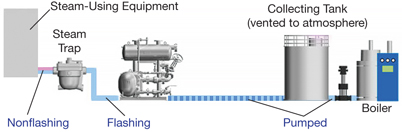
▲Figure 2. In a pumped condensate return system, the flashing condensate is discharged into a vented tank, from which the flash steam is removed. The condensate must be pumped from the vented tank to the collecting tank, and then pumped from the collecting tank to the boiler.
Figure 2 presents a pumped condensate return. Because the condensate cannot be discharged into the pressurized line easily, it is first discharged into a vented tank, from which the flash steam is removed. That portion of the system, up to the tank, is very similar to a gravity return system. However, after the vented tank, the condensate must be pumped from the vented tank to the collecting tank, and from the collecting tank to the boiler.
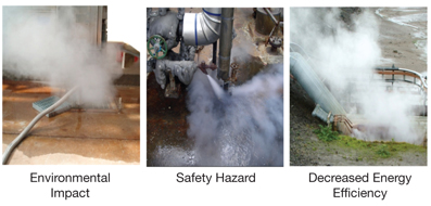
▲Figure 3. There are many places in plants where condensate is not recovered. This can create a negative environmental impact, pose a safety risk, and reduce the energy efficiency of the plant.
In some plants, a significant amount of condensate is wasted. Therefore, any discussion regarding the importance of effective condensate recovery should consider basic economics. Steam trap manufacturers offer free tools to estimate the monetary value of recoverable condensate. In addition, returning treated water enables the plant to more closely maintain a good chemical balance. For example, it is easier to provide proper chemical treatment if only 40% makeup water is needed than if 80% makeup is required. Also, having hot condensate returned not only saves energy, but also reduces the steam load on the boiler, which can be extremely important in plants where the steam demand is already near the capacity of the system. Still, there are plants that do not recover all of their condensate (Figure 3), and these plants have excellent opportunities for improvement.
Some of the reasons given for not returning condensate include that the return lines are deteriorated or so internally narrowed that they are no longer able to handle the condensate loads. Such conditions reinforce the need for better return practices. The returns are less likely to suffer corrosion if chemical treatment is more accurate and the desired system pH is maintained; it can be much easier to obtain the proper acid-base balance when less makeup water is used.
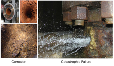
▲Figure 4. Corroded pipes in condensate return systems are more susceptible to leaking and catastrophic failure, especially if they are subject to shock from water hammer.
Additionally, corroded pipes experience more external leaks and failures (Figure 4), and those can be exacerbated by water hammer.
Water hammer in steam and condensate systems
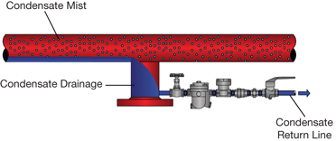
▲Figure 5. Properly installed condensate discharge locations facilitate a steam trap’s ability to remove, drain, and return condensate, vent noncondensable gases, and help eliminate water hammer in steam lines, while preventing steam loss through the location.
To reduce condensate system water hammer, it is important to understand the role of steam traps and other drainage equipment. A steam trap has a clearly defined role — to discharge noncondensable gases and condensate without leaking steam (Figure 5).
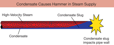
▲Figure 6. In a steam supply system, violent water hammer occurs when slugs of liquid condensate close off the cross-sectional pipe area and are propelled by high-velocity steam against piping walls. Thus, condensate removal via steam traps is crucial for steam system safety and reliability.
If condensate is not removed, then dangerous water hammer can occur in the steam supply system. Water hammer occurs when slugs of liquid condensate fill the cross-sectional area of the pipe and are propelled by high-velocity steam against the pipe walls (Figure 6). Because the non-discharged condensate brings about the water hammer, condensate is the inducing factor and the hammering is condensate-induced. So, in steam supply lines, it is the liquid water itself that induces the hammer.
However, in a condensate return system, steam is usually the inducer. Hence, hammer in a condensate system is typically steam-induced. To reduce the hammer in a condensate system, the steam in the return must be addressed.
Some engineers believe that condensate return pipes are completely filled with condensate. This may be true for pumped return lines, but not for nonflashing or flashing lines. Nonflashing lines have two-phase flow, and carry both condensate and steam from the equipment to the trap. Flashing lines also have two-phase flow — carrying both drained condensate and flash steam generated by high-temperature condensate discharging into a lower-pressure system. Steam can also enter a condensate system when steam traps require maintenance and leak, when bypass lines are open, or when outlet control valves remain open.
When flash steam or small amounts of live steam are present in a condensate return, the volume of the steam pocket can be large even if the steam mass is small (due to steam’s much greater specific volume). Because the pocket’s mass is much smaller than the mass of the condensate, heat flows quickly from the steam to the condensate, which causes the pocket to collapse. The collapse can be rapid — creating a localized, extremely low-pressure void, which condensate races to fill. When the void is full, the rapid backfill movement is redirected to the pipe wall, and its momentum creates shock waves that are heard as hammering (Figure 7).
b.
▲Figure 7. (a) Steam from either flashing, trap leaks, or opened valves in a condensate return line forms large pockets, even though the steam mass may be small. (b) The mass of condensate is relatively high, pulling heat from the steam, which causes the steam pockets to collapse, thereby creating a localized low-pressure void. Condensate races to fill the void from all directions, and the rapid backfill movement slams against the pipe wall, creating shock waves and a hammering sound.
a.
▲Figure 8. Usually, a significant portion of condensate exiting a steam trap flashes into steam upon discharge. The flash steam condenses when it mixes with other condensate in the return, and, if the return line is not suitably designed, hammer can occur when the void created by the discharged steam collapses.
Consider how this applies to the discharge from process equipment. When a large condensate flow exits a steam trap, a significant portion of it can flash and mix with the other condensate in the return line. The steam eventually must condense due to the flow of heat to the larger condensate mass. If the return is a pumped line or at a low temperature, or if there is no other steam in the return line, then it is possible that hammer could occur as the void created by the steam pocket collapses (Figure 8).
Flash steam in the condensate return
▲Figure 9. High-temperature condensate flashes immediately at the orifice outlet as it is discharged into a lower-pressure system.
Flash steam is created whenever the temperature of the hot condensate on the inlet side of the trap is higher than the saturated steam temperature on the outlet side. In such instances, flashing happens immediately at the orifice discharge (Figure 9).
▲Figure 10. When condensate is discharged from 145 psig to atmospheric pressure, a tremendous amount of flash steam is generated. However, when condensate at the same pressure is discharged to a closed system at 44 psig, much less flash steam is generated.
The amount of flash steam created depends on several factors, and it is significantly less when the pressure drop is lower. For example, the steam trap on the left side of Figure 10 discharges condensate from a 145-psig condensing source into an atmospheric pressure (0 psig) return, while the trap on the right side of Figure 10 has the same inlet pressure but discharges into a pressurized return holding 44 psig backpressure.
When condensate is discharged from a high pressure to atmosphere, a tremendous amount of flash steam can be generated. Due to its large volume, this flash steam is sometimes mistaken for leaking steam. On the other hand, when condensate is drained into a closed return, much less flash steam is created. To properly size the return piping, it is necessary to determine the amount of flash steam produced so that the pipe volume is sufficient for two-phase flow.
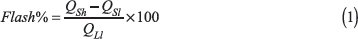
Fortunately, there is a simple way to calculate the amount of expected flash steam generated. High-temperature, high-pressure condensate discharged to a lower-pressure return contains more sensible heat than water at its saturation point at the lower pressure. The excess (latent) heat causes some of the condensate to vaporize to flash steam:
where Flash% is the percentage of condensate that flashes steam, QSh is the sensible heat at high pressure, QSl is the sensible heat at low pressure, and QLl is the latent heat at low pressure.
Equation 1 can be used to calculate the amount of flash steam (i.e., the percentage of condensate that flashes to steam) for the steam traps in Figure 10. At 145 psig, QSh = 336.0 Btu/lb; at 0 psig, QSl = 180.2 Btu/lb and QLl = 970.3 Btu/lb; and at 44 psig, QSl = 260.8 Btu/lb and QLl = 916.8 Btu/lb. So, for the trap on the left, with a discharge pressure of 0 psig:
and for the trap on the right, where the discharge pressure is 44 psig:
The atmospheric return line handles condensate that is 16 wt% flash steam, while the pressurized return line handles condensate containing 8 wt% flash steam. However, mass (weight) is not the critical component considered when sizing condensate return lines — the velocity of the two-phase flow in the pipe is, and that is dominated by the volume of flash steam.
Flash volume calculations are especially important in the sizing of condensate return lines in order to maintain the desired pressure and velocity. It might seem that 16% flash is not much more than 8% flash, but the specific volume of steam is much larger at 0 psig than at 44 psig. Therefore, to maintain the same fluid velocity, the required piping size for the atmospheric return line is much larger than the pressurized return line. The ratio of flash steam to condensate on a volumetric basis is 308:1 in the atmospheric return and 38:1 in the 44-psig return line.
Rather than performing the flash calculations by hand, it is easier and quicker to use the online engineering calculators that are available from steam trap manufacturers. These, as well as other tools and online videos, are useful for studying how flash steam influences pipe size.
Alternative sources of steam
Three other common sources of steam in condensate return lines are:
- leaking steam traps
- blow-through from opened bypass lines
- open condensate outlet control valves on equipment that allow steam to flow into the return header.
In the first scenario, a leaking steam trap, live steam passes through the steam trap — directly into the condensate return system. The second scenario, blow-through from opened bypasses, typically occurs when traps are undersized for the available differential pressure, or are experiencing stall conditions. When equipment does not drain condensate, the equipment’s production falters. If an operator implements a quick fix for this condition — by opening a bypass line to discharge the condensate into the return header — blow-through occurs.
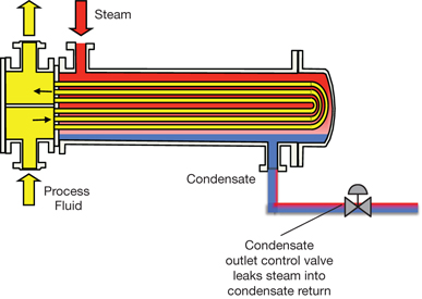
▲Figure 11. The condensate outlet control valve on a heat exchanger is often the source of much steam leakage, causing high backpressure and hammer in return lines.
The third scenario, condensate outlet control valves leaking large amounts of steam into the return header (Figure 11), may occur, for example, if heat exchange equipment is fouled and automatic settings in the controller override the level readings to keep the control valve open with the intended goal to obtain more heat. Alternatively, there might be sensor or setting errors or simply excessive control lag.
Avoid or mitigate water hammer
Some people may think that small amounts of flashing condensate can be discharged into an otherwise single-phase, completely filled (flooded) return header. However, if there is no other vapor present, that can create significant water hammer. Flash steam has a low mass — with a large volume relative to its mass — and very low energy. When it is surrounded by a huge mass of relatively cool water, the flash steam is easily dissipated and the resulting void collapse creates a shock wave.
▲Figure 12. When steam enters a return system that is filled with cooler condensate, steam pockets form. Collapsing steam pockets create violent shock waves directed to a pipe wall, causing water hammer.
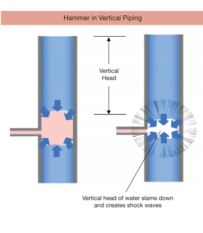
▲Figure 13. Water hammer can be worse in vertical pipes than in horizontal piping. A vertical head of water above the steam pocket can exert additional pressure on the pocket, and, when the pocket collapses, the accelerating mass of the column of water can exacerbate the shock waves.
Consider the effects of both flash steam and leaking steam from multiple traps entering a return system. The more steam added, the larger the pockets that can collect and collapse (Figure 12). Additionally, the water hammer can occur not only in horizontal piping, but also in vertical return lines, where the shock waves can be worsened by the accelerated mass of a large column of falling condensate (Figure 13).
The water hammer from steam collapse has been captured using see-through piping, posted at Ref. 1.
▲Figure 14. The backflow of steam from a two-phase condensate transport line into an equipment discharge pipe full of condensate discharging overhead can create water hammer — usually near the convergence point.
Once the circumstances of hammer are understood, it becomes easier to identify the sources and causes of shock events throughout the plant. Hammer can occur when steam flows backward from a two-phase condensate transport line into an equipment discharge pipe that is filled with water (Figure 14). This can be relatively easy to resolve by installing a check valve at the entry point to the transport header — thereby preventing the backflow.
▲Figure 15. Water hammer may occur wherever flash steam or live steam mixes with low-temperature condensate, if the condensate pulls sufficient heat from the steam and causes the pocket to collapse rapidly.
▲Figure 16. Water hammer may be generated by different steam or flash steam sources, far from or upstream of the convergence point of transport piping. In such cases, pinpointing the cause can be challenging, but it is always wise to first check for leaking traps or open bypass lines.
▲Figure 17. Flash steam from condensate should be vented through a flash vessel.
Consider the mixing of flash or live steam with low-temperature condensate in a return line (Figures 15 and 16). Hammer can be prevented in these situations by installing a flash vessel that vents the flash steam (Figure 17) and also by eliminating unnecessary steam blow-through from leaking traps or open bypass valves. The remaining flash can be vented either to atmosphere or to a pressurized flash recovery system.
▲Figure 18. Sparge pipes, which can break up flash steam into small bubbles, can be installed if it is necessary to discharge into a mostly liquid condensate line.
If the amount of condensate is relatively small and no two-phase return line can be easily reached, then you might be able to mitigate water hammer by installing a sparge pipe, which breaks up the steam into small bubbles (Figure 18). Unfortunately, there are no similar shortcuts for larger flows of flashing condensate into mostly liquid return lines.
Nonflashing condensate lines can typically be sized based on the equipment outlet size or the steam trap inlet connection size, whichever is larger. The condensate volume is relatively small compared to the pipe capacity, and the additional space enables internal balancing so that the trap does not steam-lock. Steam-locking can occur if the line size is small and the distance between the equipment and the trap is large. A pocket of steam can become trapped at the steam trap inlet while newly formed condensate builds up behind the steam pocket. The new condensate then backs up into the equipment, preventing flow into the steam trap; but more importantly, it waterlogs the equipment, thereby reducing heat or process performance.
Flashing condensate must be considered when sizing return lines flowing from the trap to a vented vessel. The volume of flash steam overwhelms the water volume in most systems and is typically the main sizing consideration. Any sizing shortcut that does not account for flash steam (or the expected amount of leakage steam from steam traps that are not functioning optimally) can cause the plant to experience difficulties.
Failure to maintain a sustainable steam trap management program can create issues with condensate return lines. The lines may be sized for flash steam and a small amount of steam trap leakage, but not a large amount of leakage. Large steam leakage increases the backpressure in the line and causes condensate to back up into process equipment, which may cause product to be off-specification. This, in turn, may prompt the operator to open the bypass valve in an attempt to mitigate the production issue, causing even more steam to leak into the return — with the probable outcome of higher backpressure negatively affecting other production equipment.
Sizing the pumped return lines is easy — simply base the size on the acceptable pipe velocity for single-phase liquid flow. But, you must be sure that no flashing condensate or live steam are discharged into the pumped return line.
Example: Undersized main return header
A new unit in a refinery incorporated a 3-in. main return header with a length of over 300 ft. The return line experienced severe hammer events for more than two years, and the site was considering a steam or nitrogen blanket to cushion the shock. Such a cushioning practice is generally not recommended — it is expensive and it increases the system backpressure. Higher backpressure can reduce the flowrate through every piece of equipment feeding into the return system, thereby limiting production.
Upon inspection, it appeared that the 3-in. header was sized for liquid flow without consideration of flashing condensate or leaking steam traps. In addition, the plant had previously stopped performing steam trap surveys and proactive repair, which most likely allowed even more steam to discharge into the header.
A technical analysis revealed that more than 90 small condensate branch lines fed into the main return header, and the combined estimated flow from those lines required a flow capability equivalent of at least 14 2-in. lines. Unfortunately, a 3-in. header has an internal volume that is only 2.24 times that of a 2-in. pipe. There did not seem to be any reasonable way that 14 2-in. equivalents could discharge into the 3-in. header without creating significant backpressure and hammer issues. Since it was not feasible to install a larger, 6-in. header, our consulting service team recommended the installation of a carefully placed flash vessel (Figure 17), to remove flash from the main header and redirect it to atmosphere.
▲Figure 19. A flash vessel can mitigate severe hammering in a condensate return header, and can also be used for low-pressure flash recovery where the system equipment allows for some backpressure.
Had the original designers considered the flashing of condensate in the main return header, then much — if not all — of the flash steam could have been diverted into a flash recovery system, and the flash steam could have been used downstream at a lower pressure (Figure 19). A system that recovered — rather than vented — flash steam would have been much more efficient and would have had a lower operating cost.
The plant was willing to pay for the technical analysis to determine the cause of the hammer, but did not allocate funds to maintain ongoing steam trap management. Reducing the leaking steam from traps in the system would have helped reduce hammer events. The first effort to reduce hammer should be to identify — then repair — leaking steam traps and close all open bypasses.
Closing thoughts
Spending the same amount of time on the condensate return system as you spend on the steam supply to the production unit can help you optimize the steam heat source to the plant. That, in turn, can help you optimize production and maximize revenue and profits.
However, proactive maintenance of the steam trap population, and effectively handling equipment stall issues, are essential to reduce the amount of steam leakage into the header, minimizing its backpressure and the negative effects on all production equipment that discharges into the same header.
Literature Cited
- “Water Hammer Caused by the Sudden Condensation of Steam,” TLV Co., www.tlv.com/global/US/steam-theory/waterhammer-mechanism.html#toc_2.
Acknowledgments
Special thanks to Hiroaki Yuri for animation production, Jeremy Galloway and Taisuke Shindo for content coordination, and Drew Mohr and Justin McFarland for graphics.
Additional Resources
“Calculator: Flash Steam Generated by Hot Condensate,” TLV Co., www.tlv.com/global/TI/calculator/flash-steam-generation.html.
“Calculator: Saturated Steam Table by Pressure,” TLV Co., www.tlv.com/global/US/calculator/steam-table-pressure.html.
“How Flash Steam Amount Influences Pipe Size,” in “Condensate Recovery Piping,” TLV Co., www.tlv.com/global/US/steam-theory/condensate-recovery-piping.html.
Risko, J. R., “Ask the Experts — Optimize the Entire Steam System,” Chemical Engineering Progress, 104 (2), p. 32 (Feb. 2008).
Risko, J. R., “Beware of the Dangers of Cold Traps,” Chemical Engineering Progress, 109 (2), pp. 50–53 (Feb. 2013).
Risko, J. R., “Handle Steam More Intelligently,” Chemical Engineering, 124 (11), pp. 44–49. (Nov. 2006).
Risko, J. R., “Steam Heat Exchangers Are Underworked and Over-Surfaced,” Chemical Engineering, 111 (11), pp. 58–62 (Nov. 2004).
Risko, J. R., “Understanding Steam Traps,” Chemical Engineering Progress, 107 (2), pp. 21–26 (Feb. 2011).
Risko, J. R., “Use Available Data to Lower System Cost,” presented at the Industrial Energy Technology Conference, www.tlv.com/global/US/articles/use-available-data-to-lower-system-cost.html (May 2011).
Risko, J. R., “Why Bad Things Happen to Good Steam Equipment,” Chemical Engineering, 122 (3), pp. 50–58 (Mar. 2015).
Walter, J. P., “Implement a Sustainable Steam-Trap Management Program,” Chemical Engineering Progress, 110 (1), pp. 43–49 (Jan. 2014).
“What is Stall?,” TLV Co., www.tlv.com/global/US/steam-theory/stall-phenomenon-pt1.html.
“What is Water Hammer?” TLV Co., Kakogawa, Japan, www.tlv.com/global/TI/steam-theory/what-is-waterhammer.html (2011).
1

Copyright Permissions
Would you like to reuse content from CEP Magazine? It’s easy to request permission to reuse content. Simply click here to connect instantly to licensing services, where you can choose from a list of options regarding how you would like to reuse the desired content and complete the transaction.