
Sections
Use this methodology to select a dilute or dense phase mode of pneumatic transport.
You may have come across the terms dilute or dense phase pneumatic conveying in your powders or bulk solids handling applications. Though the use of these systems to transfer bulk materials at all types of manufacturing facilities has been very common for over half a century, the selection and design process is not as well-known. Compare this to the selection of a pump for a liquid or gas, where proven design methods and best practices are ubiquitous, provided accurate definition of the fluid and the equipment requirements.
Pneumatic transport remains a popular conveying technology compared to mechanical systems (e.g., screws, belts, and drags) because of the benefits of flexible arrangements, product containment, low maintenance, and ease of automation. Though many advances have been made to pneumatic conveying systems, problems of insufficient capacity, plugging, line buildup, pipeline wear, particle attrition, and excessive energy consumption still plague many operations.
Furthermore, the selection and design process for dilute or dense phase systems is not generally taught to engineers at universities. Thus, users of the technology often rely on equipment suppliers, prior applications, and in some cases, trial-and-error. Poorly designed pneumatic conveying systems can be unreliable and inefficient, and may even be unsafe. Compounding the difficulty of careful design is the fact that pneumatic conveying relies on a system instead of a single equipment component, like a pump. Key components of the gas flow generator, solids hopper/feeder, pipeline/valves, and filter all play a role in effective operation of a pneumatic conveying system (Figure 1). A systems approach is vital when selecting a pneumatic transport system.
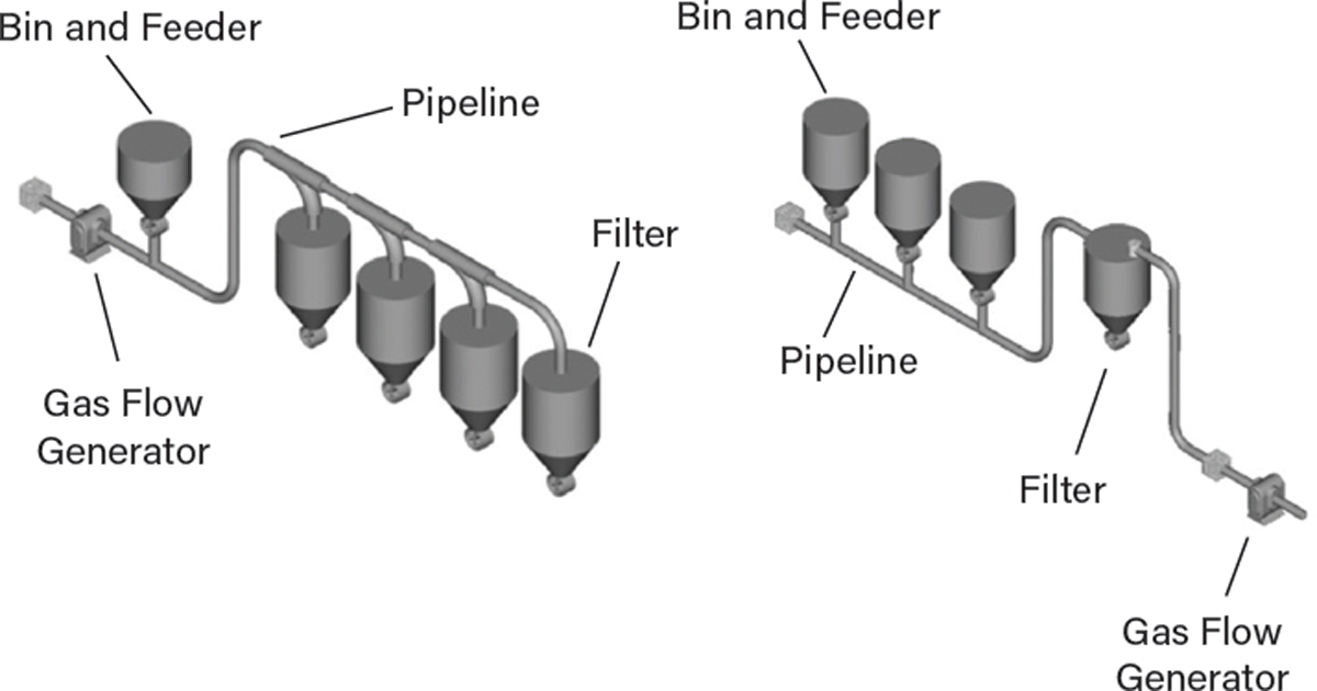
▲Figure 1. In a positive pressure pneumatic conveying system (left), gas is being “pushed” through by a gas flow generator at the start of the system, whereas in a vacuum conveying system (right), gas is being “pulled” through by a gas flow generator at the end of the system.
Experience proves that the most important step in selecting a dilute or dense phase pneumatic conveying system is the thorough evaluation of the powder or bulk solid. This may seem obvious; however, systems are often implemented with minimal consideration of the solids, which can result in major failures costing time and money.
This article is meant to assist new users of this technology in making informed decisions when selecting a dilute or dense phase pneumatic conveying system. Separate articles by this author are available focusing more on advanced topics of system troubleshooting (1) and calculation of pressure drop in a pneumatic conveying line (2).
Pneumatic Conveying Terminology
Numerous terms are used to describe gas/solids flow and pressure conditions within a pneumatic conveying system. The basic terminology is described here:
Saltation velocity. This is the gas velocity at which particles that are fully suspended within a horizontal conveying line begin to drop out of suspension and settle in a layer on the bottom of the pipeline. Choking velocity is similar to saltation, except it is in the vertical orientation.
Dilute phase. This occurs when particles are conveyed in the gas stream at a velocity that is greater than the saltation velocity. This type of system is often referred to as a stream flow system because particles are fully suspended in the gas stream. Many bulk solids can be conveyed in dilute phase; however, potential adverse effects such as pipeline wear or particle attrition could occur due to high conveying velocity. Dilute phase also refers to the lean solids loading within the conveying line. Typically, a dilute phase line conveys less than 15 lb (~7 kg) of solids per pound (~0.5 kg) of gas at a pressure of less than 15 psig (~1 barg).
Dense phase. This occurs when particles are conveyed in the gas stream at a velocity that is less than the saltation velocity. Two modes of flow can result in dense phase, namely piston/plug flow and moving bed flow. Only certain powders or bulk solids can be effectively conveyed in these two dense phase modes. In plug flow, coarse, permeable bulk solids like pellets or catalyst beads can be reliably conveyed, whereas with moving bed flow, fine and air-retentive bulk solids like cement or fine ash can be effectively conveyed. Dense phase also refers to the solids loading within the conveying line. Typically, a dense phase line conveys more than 15 lb of solids per pound of gas, at pressures greater than 30 psig (~2 barg).
Major advantages of a dense phase system over a dilute phase system include: reduced conveying gas velocity (yielding less pipeline wear and particle damage); lower gas requirements; lower operating (energy) costs; and longer conveying distances. Note that transport in dense phase conveying does not mean that particles are settled throughout the entire line; in fact, the expansion of the gas through the conveying line allows the tail-end of the system to operate as in dilute phase, even though the initial portion of the line operates as dense phase.
Pickup velocity. This is the gas velocity at the pickup point of the conveying system where solids are fed or discharged into the conveying gas stream. In some cases, this is the gas velocity necessary to pick up, suspend, and entrain particles in a settled layer on the bottom of a horizontal pipeline. The former definition applies for this article.
Pressure vs. vacuum. A positive pressure conveying system utilizes gas pressure above atmospheric pressure to entrain the bulk solids and transport the material to either one or multiple destinations (often at atmospheric pressure). Conversely, a vacuum conveying system picks up solids at atmospheric pressure (often from multiple locations) and discharges the material into a vessel that is at a pressure less than atmospheric (hence vacuum). Positive pressure systems can operate at high pressure levels and convey materials over long distances. Vacuum systems are typically limited to less than 300 ft (~90 m), though some systems have greater capabilities. Vacuum systems are also well-suited for handling dusty or toxic materials, given that any leakage in the pipeline will be inward. Some specialized systems incorporate features of both positive and negative pressure conditions, such as pull/push systems. Figure 1 provides an illustration of pressure and vacuum systems with their primary components of the gas flow generator, feeder, pipeline, and filter.
Background
Before discussing the methodology for selecting a dilute or dense phase conveying system, it is important to review the physics involved with transporting particles in a gas flow through a conveying line. Note that it is not the presence of a vacuum or pressure condition in a conveying system that imparts motion to the bulk solids, rather, it is the drag force. The drag force (FD) on a particle, as shown in Eq. 1(3), is a function of several factors, including the drag coefficient (CD), gas density (ρG), particle projected area (AP), and the square of the gas velocity (VG).

The drag force is strongly dependent on velocity; this concept can be demonstrated by running a leaf blower at an idle engine vs. at high throttle, where the leaves are easily moved. The drag force equation also provides some insight into why dense phase transport can be more effective at moving particles at the solids ingress to the system than vacuum transport. Vacuum systems often pick up solids near atmospheric pressure conditions with substantially lower air density than dense phase systems, which operate at 45–60 psig (3–4 barg). The gas density is proportionally higher with increased pressure, as per the ideal gas law. This increase in gas density helps to push the particles more efficiently through the conveying line at lower gas velocities. Additionally, the particle-on-particle forces in the gas/solids dense phase condition can assist with transport efficiency.
Step 1: Gather information
The first step in deciding between dilute or dense phase conveying is to gather as much information as possible about the application. Develop a high-level objective or system purpose statement to help guide the selection process. You may also need to conduct assessments to determine key factors such as project capital, operating costs, maintenance needs, reliability, operating complexity, and safety requirements.
Define information about the conveying system layout with emphasis on distance, lift or descent, instantaneous and averaged throughput, integration with feed and delivery equipment, and interferences. It is also important to define environmental conditions for local elevation above/below sea level, ambient temperature ranges, and relative humidity (when using unconditioned air for pneumatic transport).
Step 2: Determine material characteristics
With almost all powder and bulk solids conveying equipment selection and design applications, experts will tell you it is all about the material. Bulk solids can be classified in a variety of ways to help describe their behavior in conveying systems. Look at the range of conditions of the solids in Figure 2 alone.
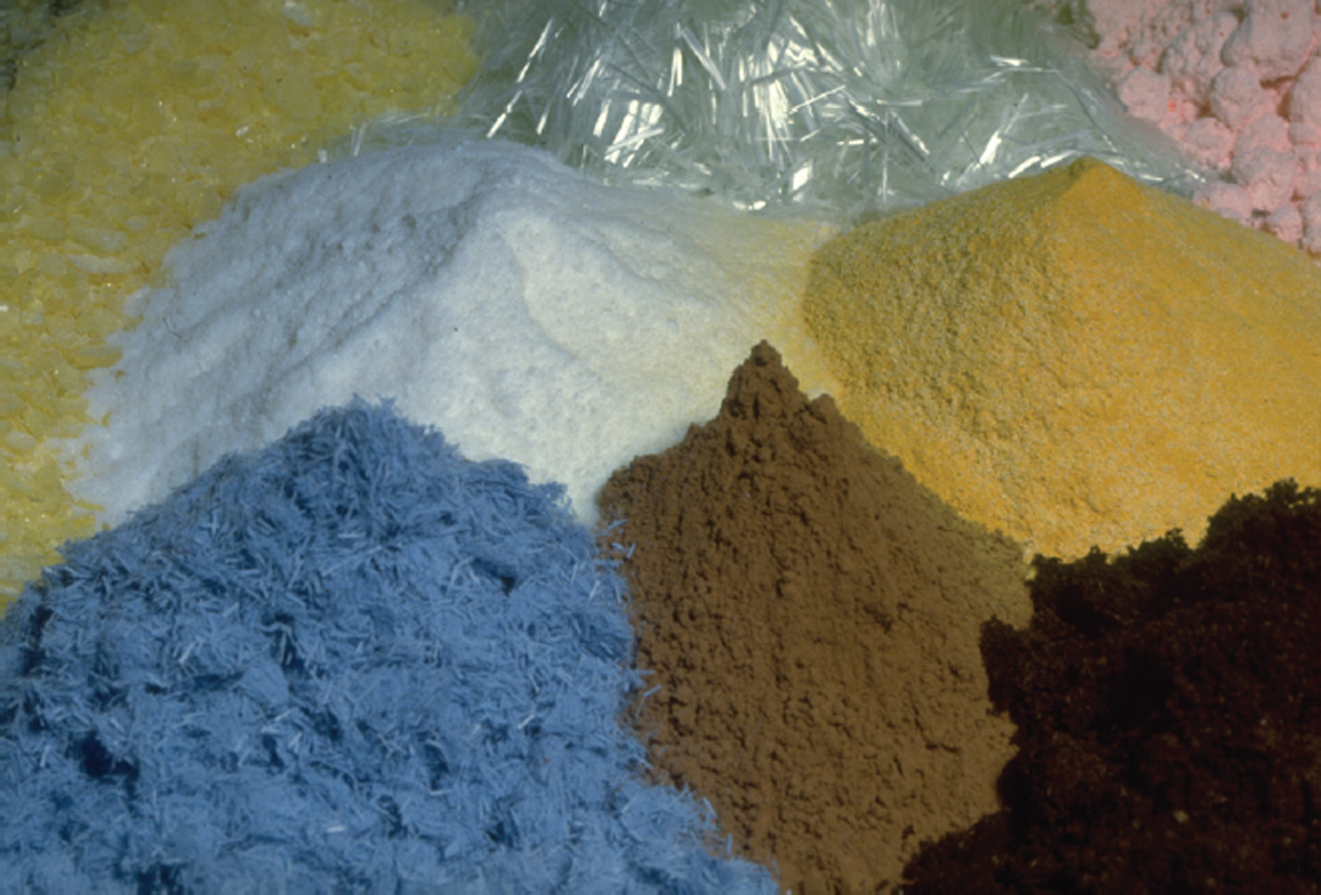
▲Figure 2. Powders and bulk solids come in a wide variety of shapes and particle sizes.
Size and shape. These can be determined through many methods, including sieve analyses, imaging/microscopy, settlement, and dry/wet laser diffraction. Knowing the particle top size, average size, and percent of “fines” are important parameters for conveyor selection. For example, if you are moving 6-in. (15-cm) lumps, a pneumatic system may not be a practical choice.
Permeability, fluidization, and deaeration. These behaviors categorize how a powder or solid interacts with air or other gases. Permeability is the resistance of gas flow through a packed bed of solids, whereas fluidization is the ability of a material to take on a fluid-like nature during gas incorporation to a packed bed. Deaeration of a solid considers the time for a material to settle after it has been fluidized. These factors are helpful when assessing pneumatic conveying suitability.
Cohesion and stickiness. The tendency for particles to stick to themselves and other surfaces can be an important factor for conveyor selection. In some cases, extreme cohesion can prevent the feeding of solids into a pneumatic conveying system, and consequently, a mechanical conveying system may be required.
Friction. The coefficient of sliding friction between bulk solids and a conveyor’s boundary surface (e.g., a steel pipeline or a rubber belt) can be a factor in not only conveyor selection but also its operational energy requirements.
Compressibility and bulk density. The compressibility of a bulk solid is its bulk density over a range of pressure. Granulated sugar is not compressible, whereas sawdust is highly compressible. The particle density of a bulk solid is related to its bulk density, and the bulk density can be an important factor in the selection and design of conveyors.
Abrasiveness. Many abrasive bulk solids (e.g., sand, fly ash, or gravel) can become strongly erosive in pneumatic pipelines during transport, so other conveyors may be more suitable. Abrasiveness is a function of a solid’s pressure, velocity (often a power law behavior), and the relative difference in hardness between the particles and a surface.
Attrition and friability. A bulk solid’s ability to resist breakage can be quantified through specialized testing. Particle attrition or friability can be measured under scenarios of impact, shear, rubbing, and compression. A comparison of the particle size pre- and post-testing to assess size reduction can assist with qualification or quantification of attrition.
Segregation. This is the separation of particles into groups of particles by size, shape, or density. Several mechanisms of segregation exist industrially. Sifting, fluidization, and dusting are the most common (4).
Toxicity, reactivity, and explosibility. Many bulk solids can present hazards to life and property. Fine powders have a high surface-area-to-volume ratio, which means they can be subject to strong chemical reactivity and biological exposures, as well as a higher risk of flash fires and dust explosions. Materials considered relatively benign in bulk can pose toxicological, ecological, and explosion risks when suspended in a finely divided form. For example, aluminum powder in dust form is far more dangerous than an aluminum car tire rim. A material safety data sheet (MSDS) provides the basic risks associated with a material and should be a first point for a hazard assessment when it comes to conveyor selection. The MSDS includes safety information such as:
- available information about the product, including composition for physical and chemical properties, stability, reactivity, toxicology, ecological concerns, and regulations.
- hazard identification, including emergency overview, acute effects, chronic effects, and overexposure signs and symptoms.
- measures for exposure controls, personal protection, first aid, firefighting, labeling, housekeeping, disposal, and accidental releases.
- combustibility and explosibility.
For a fire to start, three elements must be present — a fuel, an oxidizer, and an ignition source. Together these form the fire triangle. When these three elements are present, a fire (combustion) occurs. For a combustible solid to explode, two additional elements are required: particle dispersion (typically dust) in sufficient concentration and confinement of the cloud. In combination, these five elements (referred to as the dust explosion pentagon) can cause an explosion.
Step 3: Navigate the conveyor selection flowchart
Selecting a mechanical or pneumatic conveyor, whether dilute or dense phase, is not always straightforward, and is generally not taught to undergraduate engineers. Yet, engineers entering the workforce are occasionally tasked with determining the most suitable conveyor for handling powder or bulk solids between unit operations. Chemical engineers may be tempted to gravitate toward pneumatic conveying systems because they involve piping; however, moving solids through pipes is usually not as predictable and scalable as liquids or gases because bulk solids have unique behaviors.
The author proposes a basic flowchart to assist engineers, operators, project/plant managers, and process owners in selecting a suitable conveying system (Figure 3). The flowchart focuses on decision points based on the evaluation of the operating system or key bulk material factors. This decision tool is not meant to handle every application imaginable; rather, it is suitable for most cases where engineers need to decide between a mechanical or pneumatic conveyor, and whether that pneumatic system should be dilute or dense phase. The flowchart also assists with selecting the dense phase system as either piston/plug or moving bed — an important determination. Lastly, the chart helps with determining vacuum or pressure dilute conveying.
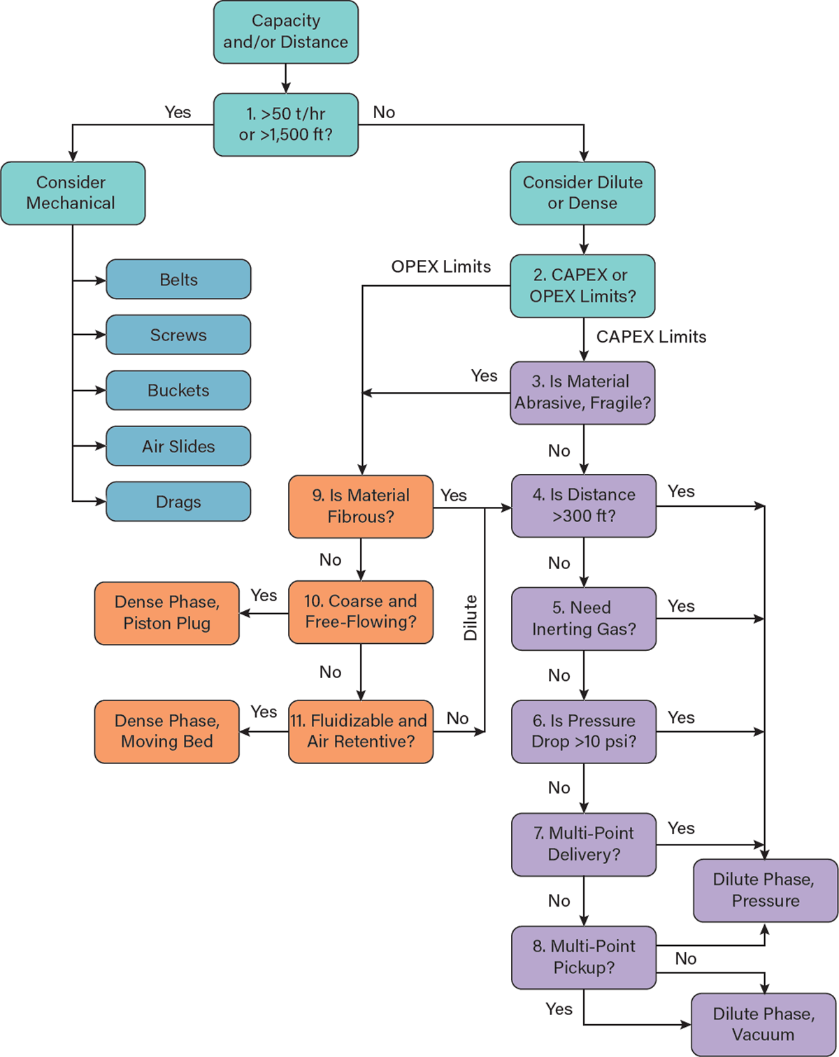
▲Figure 3. Use this flowchart to select the pneumatic conveyor that is most suitable for your application.
Decision 1: Capacity needs. The transport capacity of the conveying system is vital to consider as it can be one of the simplest ways to determine whether a mechanical or pneumatic conveying system is required. As shown in the conveyor selection flowchart, having a transport system requirement exceeding either 50 t/hr (~45 m.t./hr) or 1,500 ft (~460 m) will generally guide you toward a mechanical conveying system, such as a belt or screw conveyor. Other mechanical conveyors such as bucket elevators, air slides, and drags can also handle high tonnage rates and/or long distances. Pneumatic conveying systems have the highest specific energy consumption due to the energy from moving large volumes of air. With pneumatic conveying systems using air or gas for particle transport, exceeding these limits is possible with specialized technology and design features.
Decision 2: CAPEX/OPEX. If a pneumatic conveying system is practical for selection based on the tonnage rate or distance assessment, then the next decision point pertains to the available capital expenditure (CAPEX) and expected operating expenditure (OPEX). As shown in the conveyor selection flowchart, if your project is limited in CAPEX funding, then it may be prudent to consider a dilute phase transport system. The overall equipment costs of a dilute phase system can be lower than a dense phase system because pressure vessels, specialized heavy-duty valves, and flanged piping connections are not required. If your project is limited in OPEX (whether due to high energy costs to generate gas/air flow or expected maintenance costs), then selecting a dense phase system may be feasible as less gas/air is required for conveying. However, depending on the pressure required for effective dense phase transport, the energy needed to generate and condition 45–60 psig (3–4 barg) pressure can be significant.
Decision 3: Velocity effects. Assuming the CAPEX/OPEX decision leads you toward dilute phase transport, then careful consideration should be made to the effects of conveying velocity on either the pipeline or the bulk solid, yielding erosion (abrasive wear) or attrition, respectively. Pilot-scale tests can be performed by equipment suppliers, consulting engineering firms, or research companies to assess wear and attrition effects with dilute phase in either vacuum or pressure modes of conveying. If test results demonstrate pipeline or particle damage beyond acceptable levels, then the flowchart directs you back toward a dense phase conveying approach. If both wear and attrition are not expected to exceed allowable limits with dilute, then further progression down the dilute phase transport approach is recommended.
Decision 4: Distance (dilute). Assuming that dilute phase is feasible, the conveyor selection flowchart now assists you with determining if either a pressure or vacuum dilute phase system is practical. The first limiting factor in this assessment is the conveying distance of 300 ft (~90 m). Exceeding this distance can be challenging for a vacuum dilute phase conveying system due to limitations in maximum pressure drop across the line. If the distance exceeds 300 ft for conveying, then it is recommended to consider dilute phase pressure mode of transport. Note that on earth, we are limited to a maximum vacuum of 29.9 in. of Hg (realistically, 20 in. of Hg limit in most industrial systems), but with pressure systems, we can go relatively high as long as the equipment is designed to withstand the pressures. Again, exceptions to these suggested limiting values do exist, as this conveyor selection flowchart is not meant for all cases.
Decision 5: Inert gas (dilute). Assuming that dilute phase remains feasible, the conveyor selection flowchart inquires about the need for inerting gas based on combustibility or explosibility considerations, or possibly due to the oxidation or relative humidity effects that can be common with a vacuum transport system. If inerting gas is required, then a pressure dilute phase system is warranted because ambient air (with oxygen) is not likely to enter the conveying line (i.e., pressure in the line will be higher than outside). Note that if the material is toxic, vacuum transport may be safer, given any line leakage is inward.
Decision 6: Pressure drop (dilute). Assuming that dilute phase remains feasible, the conveyor selection flowchart considers the limitation of pressure drop with vacuum dilute phase. If the system resistance (pressure drop) is estimated to be greater than 10 psi (20 in. Hg), then a pressure dilute phase system is recommended for reasons described previously in Decision 4.
Decision 7: Delivery (dilute). Assuming that dilute phase remains feasible, the conveyor selection flowchart considers if multiple delivery locations are likely. A pressure conveying system is typically more practical with delivery locations near atmospheric conditions. Vacuum dilute phase can deliver to multiple locations; however, it can be more challenging with filtering and piping arrangements, as well as structural implications with equipment designed for vacuum.
Decision 8: Pickups (dilute). Assuming that dilute phase remains feasible, the conveyor selection flowchart considers if multiple pickup locations are likely. A vacuum conveying system is ideal for multiple pickup locations because it feeds at near atmospheric conditions at each pickup, avoiding the need for large pressure drop sealing technology across the feeder. One example of a dilute phase vacuum conveyor is a dust collection unit.
The next sections focus on assessing the suitability for dense phase conveying based on material characteristics. The famous adage of “many, many bulk solids can be conveyed in dilute phase transport provided sufficient conveying velocity…” is helpful to consider, but with dense phase, many material factors can readily prevent its selection. Three possible outcomes can result through the dense phase conveying decision path: dense phase piston plug, dense phase moving bed, and dilute phase (either pressure or vacuum).
Decision 9: Fibrous material (dense). Assuming that velocity effects will be an issue with dilute phase and/or that the system is OPEX-limited, the conveyor selection flowchart pivots toward the dense phase path. One key early decision point with dense phase is if the material is fibrous or interlocking (e.g., wood chips, straw, or chopped fiberglass). These types of materials do not feed reliably from dense phase pressure vessels (e.g., blow pots, transporters, pods), and thus starve the line during feeding. Second, fibrous materials do not move as moving beds or pistons through a conveying line because they tend to bunch together and compress, forming an immobile plug; thus, these types of materials are better suited for dilute phase conveying.
Decision 10: Coarse material (dense). Assuming that fibrous material is not handled, then the flow chart continues with an assessment of particle size and cohesion (5, 6). If the bulk solids are coarse (i.e., greater than 1/8 in. or 3 mm with a near mono-disperse distribution) and free-flowing (i.e., no bridging and ratholing tendencies), then dense phase piston plug transport is likely suitable. Candidates for this type of conveying include plastic pellets, coffee beans, and seeds. In each case, the materials do not stick to each other, and they allow air/gas flow through the discrete piston plugs to allow reliable dense phase operation.
Decision 11: Air-retentive material (dense). Assuming that material is not coarse and free-flowing, then the conveyor selection flowchart continues with an assessment of the material’s ability to fluidize and retain air/gas. A material can be tested to determine if it is a good candidate for fluidization and how long it takes for deaeration (7). For instance, cement powder fluidizes uniformly and deaerates slowly, meaning a moving bed mode can be effectively used for dense phase transport. On the other hand, beach sand is not only too coarse (allowing rapid deaeration and settlement), but it is also too fine, creating an impermeable long plug in a dense phase system that causes poor operability.
Geldart’s fluidization (8) and Dixon’s slugging charts (9) are also helpful resources for dense vs. dilute transport assessments. Geldart’s findings for effective material fluidization have a reasonable correlation with suitability for dense phase conveying for either piston plug or moving bed modes. However, Geldart’s classifications do not account for re-aeration technologies that may be used with specialized dense phase conveying systems using gas boosters. If the solids do not meet the coarse, free-flowing, fluidizable, and/or air retentive requirements, then the dilute phase avenue is recommended.
In closing
A wide variety of conveying technologies are available for powders and bulk solids; however, the selection process is not necessarily straightforward. This article provides a systematic and proven method to assist with conveying system selection based on key system objectives, requirements, and considerations for material characteristics.
Literature Cited
- Maynard, E., “Troubleshoot and Solve Pneumatic Conveying Problems,” Chemical Engineering Progress, 106 (6), pp. 33–40 (2010).
- Maynard, E., “Designing Pneumatic Conveying Systems,” Chemical Engineering Progress, 102 (6), pp. 22–33 (2006).
- National Aeronautics and Space Administration, “Beginners Guide to Aeronautics: Drag Equation,” NASA, https://www1.grc.nasa.gov/beginners-guide-to-aeronautics/drag-equation (accessed Sept. 16, 2022).
- Maynard, E., “Avoid Bulk Solids Segregation Problems,” Chemical Engineering Progress, 108 (4), pp. 35–39 (2012).
- ASTM International, “Standard Test Method for Shear Testing of Bulk Solids Using the Jenike Shear Cell,” Annual Book of ASTM Standards, ASTM D6128-16 (2016).
- Jenike, A, “Storage and Flow of Solids,” Rev. 1980, 16th Printing, Univ. of Utah, Salt Lake City, UT (July 1994).
- Mainwaring, N., and A. Reed, “Permeability and Air Retention Characteristics of Bulk Solids Materials in Relation to Modes of Dense Phase Pneumatic Conveying,” Bulk Solids Handling, 7, No. 3 (June 1987).
- Geldart, D., “Types of Gas Fluidization,” Powder Technology, 7, pp. 285–292 (1973).
- Dixon, G., “The Impact of Powder Properties on Dense Phase Flow,” Proceedings of the International Conference on Pneumatic Conveying, London, U.K. (Jan. 1979).

Copyright Permissions
Would you like to reuse content from CEP Magazine? It’s easy to request permission to reuse content. Simply click here to connect instantly to licensing services, where you can choose from a list of options regarding how you would like to reuse the desired content and complete the transaction.