
Sections
Hydrotreating processes are becoming increasingly important as refineries work to meet more stringent environmental guidelines.
Most products of crude and vacuum distillation in refineries contain a significant amount of sulfur that must be removed prior to further processing or use. Hydrotreating or hydrodesulfurization refers to a set of operations that remove sulfur and other impurities (Figure 1). During hydrotreating, crude oil cuts are selectively reacted with hydrogen in the presence of a catalyst at relatively high temperatures and moderate pressures. The process converts undesirable aromatics, olefins, nitrogen, metals, and organosulfur compounds into stabilized products. Some hydrotreated cuts may require additional processing to meet final product specifications.
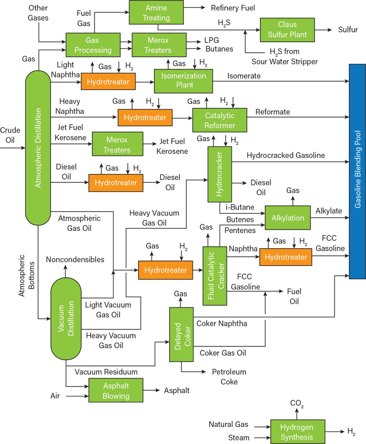
▲Figure 1. This general process flow diagram of a petroleum refinery includes several hydrotreating units.
This article explains the basics of hydrotreating processes, focusing on two of the most important petroleum products, naphtha and diesel oil. It describes how the hydrotreatment process differs between these two distillation cuts, and looks forward to what’s next in hydrotreatment as environmental standards for fuels become increasingly stringent.
Why is hydrotreatment necessary?
Petroleum refineries transform crude oil into useful fuels and products while satisfying technical, government, and safety requirements. In addition, they must comply with environmental policies that increasingly limit the amount of sulfur and other impurities in fuels. Hydrotreatment processes reduce the impurity content of petroleum products, which increases the efficiency of the fuels and reduces the production of harmful combustion byproducts such as NOx and SOx (Figure 2). Hydrotreatment also helps to satisfy final product specifications. Contaminants can affect the performance of downstream unit operations, catalysts, or even engines. One of the most common issues is nickel catalyst poisoning by sulfur, which is chemisorbed in catalytic beds.
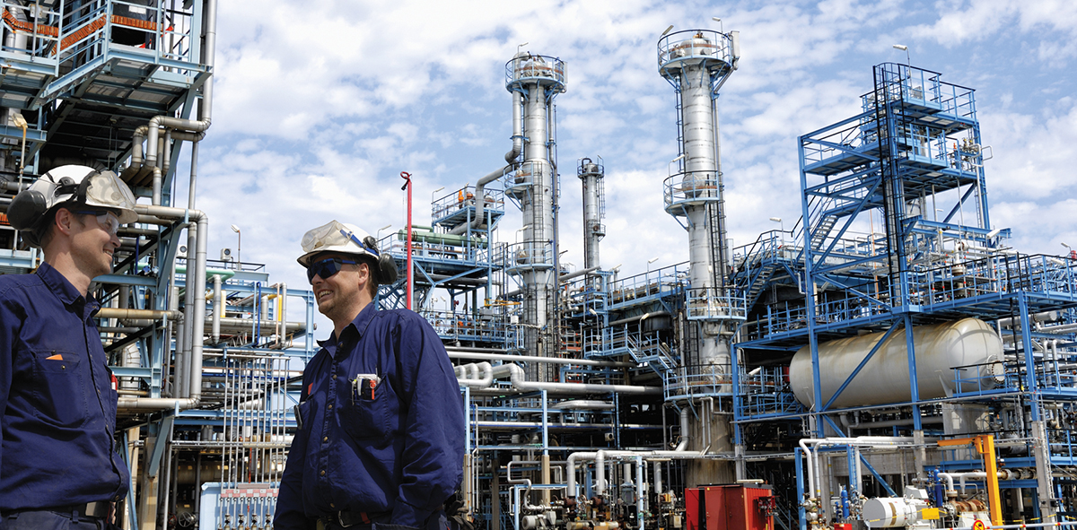
▲Figure 2. Hydrotreating processes are standard in refineries primarily to remove sulfur from refined petroleum fuels. This helps reduce sulfur dioxide emissions that are formed when the fuels are combusted.
Hydrotreating (1) is an efficient method to remove several compounds, including:
- Sulfur is the most critical compound to remove. It is present in nearly all crude oil feedstocks as sulfur mercaptans, sulfides, disulfides, polysulfides, and thiophenes.
- Nitrogen is typically treated with hydrogen gas and transformed into ammonia gas.
- Oxygen is reacted with hydrogen and eliminated as water. Most oxygen in distillation cuts is not present as oxygen gas, but bonded to hydrocarbons.
- Olefins are volatile and unstable, and they are not desirable in fuels. Olefins are transformed into stable paraffinic hydrocarbons.
- Metals are removed because they can deposit on catalysts and in engines.
The basics of hydrotreating
It is common to assume that the hydrotreating process is a single unit operation that converts all of the raw feed into a final desulfurized product. However, this is not the case; most hydrotreatment processes require many unit operations, including a reactor, gas separators, separation columns, and heat exchangers. The process can be divided into three main processing blocks:
- heat exchange network
- reactor in which the actual hydrotreating takes place
- stripping where the desulfurized product stream is separated from the volatiles, gases, and impurities.
Each hydrotreating unit is tailored to the feedstock and end product. For instance, the process to hydrotreat naphtha is not the same as the process for diesel fuels. The most common cuts that are hydrotreated in a refinery include: light naphtha, heavy naphtha, jet fuel or kerosene, and diesel oils (e.g., light and heavy coker diesel oil). This article focuses on the two main cuts: naphtha and diesel oil.
The feed is first pressurized and mixed with the recycle and makeup hydrogen streams. The mixture is heated to about 290–430°C before entering the fixed-bed reactor, which operates at about 7–180 bar. Higher temperatures and pressures are used for processing heavier feedstocks, such as diesel oils. Overall, however, hydrotreater temperatures are relatively moderate, which avoids thermal cracking of molecules while being high enough to enable reaction of the feedstock.
Inside the fixed-bed reactor, hydrogenolysis and mild hydrocracking reactions take place to convert sulfur, nitrogen, oxygen, and other contaminants to hydrogen sulfide, ammonia, water vapor, and other stabilized byproducts (Figure 3). The catalyst used in the reactor is a crucial design consideration that greatly affects the final products. If sulfur removal is the primary goal, cobalt-molybdenum catalysts are favored. If the crude oil is relatively low in sulfur, nitrogen removal becomes the priority and nickel-molybdenum catalysts are chosen. Depending on the conditions and composition of the outlet streams, the byproducts are either discarded, recycled, or sent for further treatment.

▲Figure 3. Common hydrotreating unit reactions convert impurities to stabilized products in the presence of excess hydrogen (1).
Most outlet streams undergo further treatment to lessen their environmental impact and/or recover the material for use. Sour gas (which contains hydrocarbons, carbon dioxide, and a significant amount of hydrogen sulfide) is commonly sent to an amine gas treating unit that separates the hydrocarbon gases from the hydrogen sulfide and carbon dioxide. During amine treatment, the carbon dioxide and hydrogen sulfide are absorbed by an amine solution in the absorption unit, producing a sweet gas and amine-rich stream. The amine-rich mixture is pumped to a desorption unit where it is recovered as lean amine and recycled (Figure 4). The final product stream is a desulfurized product fuel, commonly called sweet gas.
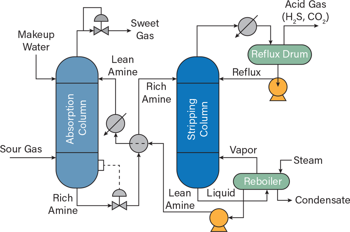
▲Figure 4. The amine gas treatment process includes an absorption unit that removes contaminants and produces a sweet gas stream and a stipping unit that recycles the amine solution.
The importance of hydrogen
Hydrogen gas is one of the most important elements in the production of desulfurized fuels. For hydrotreating, the hydrogen stream must be extremely pure (>99%) and have no humidity. The stream should have a low hydrocarbon content, as well as low mercaptan and hydrogen sulfide levels (<0.1%).
Only about 15–30% of the hydrogen demand of a refinery is produced internally by processes such as catalytic reforming of naphtha; the rest is supplied by external producers (2). The industry uses a variety of terms for hydrogen that depend on how it was produced:
- Brown hydrogen is obtained from fossil fuels such as coal or lignite via gasification. Gasification has a large carbon footprint, but remains a common way to produce hydrogen.
- Gray hydrogen is obtained from natural gas via steam-methane reforming, and has a smaller carbon footprint than brown hydrogen. It has become the most common type of hydrogen due to low prices for natural gas.
- Blue hydrogen is commonly produced from methane, but differs from gray hydrogen in that the resulting carbon emissions are captured and sequestered. Due to environmental restrictions, blue hydrogen is becoming more common.
- Turquoise hydrogen is produced from a feedstock of pure methane via pyrolysis. It is associated with a very small carbon footprint, because pyrolysis byproducts include only solid carbon and no carbon dioxide.
- Green hydrogen is produced from any renewable energy source, such as electrolysis of water via windmills or solar energy. It has not gained traction due to technology challenges and high prices.
Hydrotreating naphtha
Naphtha is a valuable product of petroleum refining, as it is one of the main constituents of the gasoline blending pool. While there is no formal definition of naphtha, it is commonly considered the C5–C12 cut, which is divided into light and heavy naphtha. Light naphtha has an initial boiling point (IBP) of about 30°C and a final boiling point (FBP) of about 145°C. It contains most of the hydrocarbons between C4 and C6. Heavy naphtha has an IBP and FBP of about 140°C and 205°C, respectively. It contains most of the hydrocarbons in the C6–C12 range.
High sulfur content is associated with cuts that are heavier than naphtha. However, removing the relatively small amount of sulfur in naphtha is beneficial for engine performance and operational longevity. Figure 5 presents a flow diagram of the hydrotreating process for naphtha (3).

▲Figure 5. This flow diagram shows the hydrotreating process for naphtha.
Heating. The naphtha feed enters the hydrotreatment unit through a charge pump. It is first mixed with hydrogen gas from either the catalytic reforming unit (CRU) or refinery hydrogen plant. The mixture is then heated to 340°C while being contacted with the reactor’s effluent.
The charge heater has four passes with four gas burners. Heater tubes are constructed of Type 321 stainless steel, which is the grade of choice for applications with temperatures up to around 900°C, because it combines high strength and resistance to scaling with resistance to aqueous corrosion.
Reaction. After preheating, the mixture is fed to a reactor with two catalyst beds. The desulfurization reactions take place over the cobalt-molybdenum bed and the nitrogen reactions take place over the alumina bed. The reactor temperature is held at a constant 315°C and a pressure of 370 psig.
The reactor effluent contains mostly the desulfurized naphtha, excess hydrogen, hydrogen sulfide, ammonia, and light hydrocarbons (C1–C4) due to mild cracking. The reactor effluent is cooled and partially condensed through a feed/effluent heat exchanger and then cooled with air.
Separations. The separation process, or stripping section, uses a series of separators and columns to stabilize the naphtha.
The cooled stream from the reactor is sent to a pressurized flash separator at 290 psig. The light ends, mainly hydrogen sulfide, ammonia, excess hydrogen gas, and light hydrocarbons, are separated from the bulk of the desulfurized naphtha.
The liquid naphtha stream from the separator is then sent to the stripping unit. The stripping column is heated to 340°C by a reboiler and held at a pressure of 205 psig. High temperature and pressure enable removal of volatile material (light hydrocarbons), which would vaporize at final storage and use conditions. Inlets to the stripping column include desulfurized raw naphtha, recycled desulfurized stripped naphtha, and the bottoms of the column. The outlet streams include mostly light gases (C1–C5 hydrocarbons) that are sent for amine treatment to recover them as fuels.
The resulting liquid naphtha is then cooled by air and sent out of the unit’s battery limits as stabilized hydrotreated naphtha product.
Hydrotreating diesel oils
Diesel oil may be either a direct cut from the atmospheric distillation column or a mixture of light cycle oil from the fluid catalytic cracker (FCC) unit and heavy cycle oil from the delayed coker. These cuts contain 1–2% sulfur (10,000–20,000 ppm) — much higher than the fuel requirement of 10–15 ppm.
Therefore, hydrotreating is one of the most important steps of processing diesel oils to specification, as it removes sulfur and other impurities such as nitrogen and olefins. In addition, hydrotreating saturates olefins (removal of double-bonded carbons) within the diesel oil. This process increases the stability and decreases volatility of the diesel, enabling longer storage.
The process of hydrotreating diesel oil cuts is much more complex than that of naphtha, primarily due to the addition of the regenerative amine system, which recovers excess hydrogen gas and removes hydrogen sulfide via diethanolamine (DEA). Figure 6 presents a flow diagram of the hydrotreating process for diesel oil.

▲Figure 6. This flow diagram shows the hydrotreating process for diesel oil.
Heating. The raw untreated diesel oil is pumped directly to the heat exchange network. Hydrotreating processes are designed with heat exchange networks that pair the low-temperature feed to the reactor, which requires heating, to the high-temperature reactor effluent that requires cooling.
Reaction. The heated feedstock is mixed with a hot recycle hydrogen stream recovered from downstream processes, and the mixture is sent to the reactor. Depending on the sulfur content of the stream, either a cobalt-molybdenum bed (sulfur removal) or nickel-molybdenum on alumina bed (nitrogen removal) will be used. Because high-sulfur fuels are more common in the industry today, sulfur removal is typically the focus of diesel oil hydrotreating.
The effluent of the reactor includes the offgases to be removed in the separator, light ends that will be treated and sent to the naphtha unit, and the unstabilized diesel oils.
Separations. The reactor effluent is cooled in the heat exchange network, and fresh liquid condensate from lighter cuts of the crude distillation unit is injected into the reactor effluent to avoid salt formation in downstream unit operations. The mixture is then flashed into a high-pressure separator drum, producing a liquid byproduct ammonia solution that is sent to the refinery wastewater system and a hydrogen-rich gas that contains some hydrogen sulfide.
The gases are sent to an absorber that removes the hydrogen sulfide via a circulating DEA solution. The resulting hydrogen stream is combined with makeup hydrogen and is injected into the feedstock stream that enters the initial hydrotreatment reactor.
The now-stabilized diesel oil from the flash drum is depressurized in a successive flash drum. The process of depressurization favors gas formation, further stabilizing the liquid hydrocarbons. The flash gas is sent for hydrogen sulfide removal before going to the refinery’s fuel system.
The bottoms liquid stream from the second flash drum is preheated and sent to a stabilizer column. The stabilizer column produces three main cuts: the naphtha gas to be recovered, the recovered naphtha to be combined with other naphtha streams, and the desulfurized stabilized diesel.
Challenges and the future of hydrotreating
Hydrotreating is critical to addressing challenges refineries are facing today. Fuel consumption worldwide is increasing, putting pressure on refiners to increase production. Additionally, low-sulfur crude oils are becoming scarce, forcing refiners to contend with high-sulfur feedstocks while meeting increasingly tighter restrictions on sulfur concentrations in fuels.
Addressing this compound challenge requires the development and application of catalyst technologies that improve reaction rates, conversion, and overall performance of hydrotreating processes. Current catalysts suffer from selectivity issues that could be overcome by alternative technologies such as titanium dioxide and zirconium dioxide catalysts.
Another factor to consider is the hydrogen gas requirements of hydrotreating processes. Refineries typically operate at a hydrogen deficit, requiring purchase of hydrogen from outside vendors. As environmental restrictions become tighter, refiners will need to explore hydrogen sources with small carbon footprints.
Literature Cited
- Fahim, M., et al., “Fundamentals of Petroleum Refining,” Elsevier Science, Amsterdam, Netherlands (2010).
- U.S. Energy Information Administration, “EIA-820 Annual Refinery Report,” EIA, Washington, DC (2021).
- Rao, B., “Modern Petroleum Refining Processes, 6th Edition,” CBS Publishers and Distributors Private Limited, New Delhi, India (2018).
Additional Reading
Hussain, C., and P. Sudarsanam, “Advanced Functional Solid Catalysts for Biomass Valorization,” Elsevier, Amsterdam, Netherlands (2020).
Kalamaras, C. M., and A. M. Efstathiou, “Hydrogen Production Technologies: Current State and Future Developments,” Conference Papers in Science,2013 (June 2013).
Parkash, S., “Refining Processes Handbook,” Gulf Professional Publishing, Houston, TX (2003).
Shell International, “The Petroleum Handbook,” Elsevier Science, Oxford, U.K. (1986).

Copyright Permissions
Would you like to reuse content from CEP Magazine? It’s easy to request permission to reuse content. Simply click here to connect instantly to licensing services, where you can choose from a list of options regarding how you would like to reuse the desired content and complete the transaction.