
Modifications to conserve energy, boost plant capacity, or improve efficiency may have unforeseen impacts on flare systems. Ensure management of change (MOC) reviews do not overlook these critical safety systems.
Management of change (MOC) is a process that helps ensure changes at the plant level do not unknowingly introduce hazards or increase the risk of existing hazards (1). Plant equipment and operations are sometimes modified to conserve energy, increase capacity, or improve efficiency. It is important to study the effects of these modifications on flare systems to prevent a loss of primary containment.
This article details two case studies in which changes were made to a flare system without an adequate understanding of the potential process safety hazards associated with the changes. It also discusses some common process safety issues related to flare systems that are often overlooked during MOC reviews.
The components
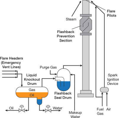
▲Figure 1. This schematic illustrates the components of a typical flare system. The manual supplied by the vendor provides a more complete picture of the flare system used at your plant.
Flare systems safely burn flammable gases vented during planned startups, planned shutdowns, and unforeseen emergencies at refineries and petrochemical plants. A typical flare system consists of a flare header, a liquid knockout drum, a flashback seal drum, a flashback prevention section, and flare pilots (Figure 1).
Flare header. The network of pipes that runs through the plant and into the flare’s liquid knockout drum is called the flare header. It collects discharge from safety valves and control valves in the plant. Purge (or sweep) gas is introduced at a specific flowrate (specified by the flare gas system supplier) at points along the header to prevent air ingress, which could create a flammable or explosive mixture.
Liquid knockout drum. The liquid knockout drum separates entrained liquid in the gas stream to prevent it from being released into the atmosphere. The drum is located at the base of the main flare structure. A pump runs automatically when the liquid level exceeds a setpoint to safely evacuate the drums.
Flashback seal drum. The flashback seal drum helps to avoid air ingress by maintaining positive backpressure in horizontal sections of the flare header. In the event of an explosion in a vertical flare stack, the flashback seal drum prevents flames from entering the horizontal flare header. The flashback seal drum is located either inside or outside the flare stack.
Flashback prevention section. The flashback prevention section at the top of the flare stack also prevents atmospheric oxygen ingress into the flare stack and thus prevents the formation of an explosive mixture.
Flare pilots. The flare pilots and the flare pilot burner ignition system keep the pilot burners continuously lit when the flare is in operation. In some flares, steam is injected through nozzles to ensure smokeless burning.
Case study 1: Fireballs
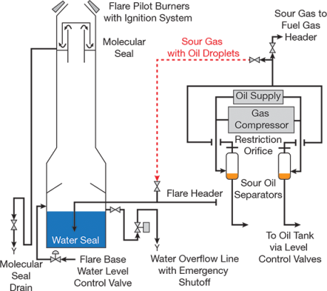
▲Figure 2. The red dotted line indicates the minor modification that routed sour gas with oil dropets to the flare header and nearly caused a disaster.
Background. An 80-m, self-supported flare stack (Figure 2) at a large methanol plant was located near major equipment. To prevent air ingress, the flare included a water seal at the base and a molecular seal at the top. Molecular seals require a continuous stream of purge gas, but the amount of purge gas is less than would be required without the seal. The molecular seal included a drain line with a U-seal and isolation valve at the bottom. The overflow line from the water seal at the flare stack base included an emergency shutoff valve that would automatically close if the level of water in the base was too low.
In another section of the plant, a synthesis gas centrifugal compressor operated continuously and included a seal oil system, which sealed both ends of the compressor rotor shaft to prevent high-pressure gas from leaking. Oil that mixed with the residual gas leaking from the compressor shaft labyrinth, called sour oil, was sent to a liquid-gas separator. The separated gas from the sour oil separators was used as fuel gas in burners elsewhere in the plant.
Incident. Progressive damage to the compressor seals caused the amount of gas leaking through the seals to increase. Droplets of oil were being carried over to the fuel gas system. An MOC was performed to evaluate the rerouting of the sour gas from the fuel gas header to the flare header. The modification used existing vent valves located on each pipeline to connect the sour gas line from the separators to the flare header.
The process hazard analysis (PHA) identified that oil would now enter the bottom of the flare. The PHA team concluded that the oil would collect on top of the water in the water seal and automatically overflow through the overflow line. The team recommended that the field operator periodically conduct a visual check to see if any oil overflowed through the overflow line of the water seal, and record the inspection in the logbook. After the change was implemented, the operators noted that they saw no oil at the flare base. No efforts were made to determine why oil was not collecting in the overflow line drain.
After more than four months of operation, the synthesis gas compressor tripped due to an unrelated fault. Prior to the compressor trip, the plant was operating at about 110% load. The emergency vent valve located upstream of the gas compressor suction opened and a large quantity of gas was vented to the flare. Balls of fire, each approximately five feet in diameter, suddenly erupted from the flare tip, fell, and ignited secondary fires around the plant. The plant commenced an emergency shutdown, and the emergency response team extinguished the secondary fires. The plant reported no injuries or fatalities.
Investigation. The investigation determined that the increased rate of gas leaking from the compressor seals carried the oil over to the molecular seal at the top of the flare. The oil started to collect in the bottom of the annular space of the molecular seal. Although the flare designer provided a drain for the molecular seal, the PHA team did not recognize that oil could be carried over when the amount of leaking gas increased, and operators never opened the valve in the drain line. The large quantity of gas vented after the compressor tripped blew the oil in the molecular seal out of the flare, and it ignited and formed fireballs.
Lessons learned. Every change introduces potential process safety hazards and needs to be evaluated by the PHA team. The team should understand the design basis of all flare system parts and make no assumptions. It is always better to consult with the original equipment manufacturer and obtain their input before proceeding with a change.
Case study 2: Internal deflagration
Background. Coincidentally, another incident involving the aforementioned methanol plant flare is relevant to this second case study. The flare in the first case study had been in operation for 14 years when operators started to periodically hear a low-frequency whoomph sound come from the flare. They heard the sound when the system was not flaring and the methanol plant was operating normally. The flare supplier advised that a mild deflagration was taking place inside the flare stack due to the ingress of air. Even after increasing the purge gas flow, operators continued to hear the abnormal sound, without external evidence of any damage. The plant was shut down, and an inspection of the flare system identified a small hole near the top of the body of the molecular seal that permitted air to bypass the molecular seal and enter the main flare stack. The hole was caused by corrosion, and repair of the hole eliminated the abnormal sound.
Incident. With knowledge of this incident, I was involved in a process safety management (PSM) audit at a large refinery 20 years later. The refinery had multiple units that were all connected to a single hydrocarbon flare system. The flare structure was emitting a low-frequency whoomph sound similar to that heard at the methanol facility. Conversations with operators revealed that the sound had been heard since a new flare gas recovery compressor was installed, but they assumed it was the noise of the compressor amplified through the stack.
Investigation. The MOC request for installing the flare gas recovery system showed that the system was a package unit, composed of a compressor and coolers, which was installed as part of an energy conservation initiative to recover and recycle hydrocarbon gases being vented. The hazard and operability study (HAZOP) indicated that the team conducted the HAZOP for the package unit but had not considered the effect of installing the compressor on the flare system.
The suction pressure controller for the compressor was incorrectly set, creating a partial vacuum in the main flare stack. In addition, the flowrate of the purge gas of the flare headers was maintained lower than recommended by the flare supplier, which allowed air ingress into the flare stack and the subsequent mild deflagration.
Lessons learned. Flare systems are a critical safety barrier and any changes must be made with complete understanding of the consequences. In any flare, two elements required to initiate a fire are already present — flammable gases and an ignition source (i.e., flare pilots). It only requires the right amount of air to raise the oxygen content inside the flare stack to a level that can initiate a fire. Plant operating personnel must be trained on all aspects of safe operation of the flare system and to report any abnormalities.
Common process safety issues
Reducing purge gas. As part of cost-saving measures, the purge gas to the flare header may be restricted or isolated without an approved MOC. In cases in which an MOC is conducted, the MOC may not consider the purge flow requirements for the period after flaring of hot gases stops. After flaring is stopped, the flare system cools down and this can reduce the pressure in a flare system, allowing air ingress. Flare designers advise a higher flowrate of purge gas during these periods.
Increasing plant capacity. Projects that remove bottlenecks to increase plant capacity do not always consider whether the flare system is adequate. At a refinery that used a common flare system for all of its units, a modification increased one plant’s capacity by 15%. An approved MOC of the modification did not evaluate the adequacy of the flare system to handle the excess gases. The MOC stopped after checking the capacity of the flare header knockout drum.
Any modification to a plant should include an MOC that evaluates the entire flare system and includes:
- pressure drop calculations and a check of the back-pressure across the flare system, as this could affect the relieving capacities of other safety valves and control valves connected to the system
- a study of the water seal at the flare base to ensure it can handle a higher flaring capacity to prevent the possibility of damaging the water seal
- a check of velocities at the flare tip to ensure there is no risk of flame liftoff, which allows unburnt flammable or toxic gases to be released into the atmosphere
- an evaluation of the main flare header knockout drums and associated pumps to determine whether they are suitable for the higher capacity
- an analysis of the effect of increased flaring capacity on the stability of the flare pilot flame
- calculation of the radiant heat from the flare tip at the higher capacity
- an evaluation of the adequacy of any smokeless flaring systems.
Misunderstanding of flare system design. Responsibility for the flare structure and its accessories is sometimes assigned to utilities personnel who receive no training on flare system design or the consequences of deviating from accepted operation. Operating plant personnel who use the flare should be responsible for the flare system. Personnel from the various plants connected to a common flare should develop a safety system checklist and review it monthly. They should also be trained on the consequences of deviating from accepted operation of the flare header, knockout drum, flashback seal drum, purge gas feed, flare pilots, and any other equipment associated with the flare.
Operating personnel often do not consider flare systems to be as important as other plant equipment. This issue is compounded by the fact that flares are usually located far from the operating plant, leaving them out of sight and, often, out of mind.
Operators may not be aware of the consequences of:
- air entering an open flange on the flare side, which may lead them to disconnect components to clear blockages when the flare is in service
- liquid carryover to the flare stack, which may lead them to restrict the opening of the discharge valve of automatic knockout drum pumps to prevent trips of the pumps’ motors
- bringing an additional safety valve into service (as part of plant capacity increase), which may cause chattering of the valves when the set pressure is reached, damaging the safety valve and its flange joints.
Conclusions
A flare system is a critical defense at a chemical plant or refinery, and understanding the design basis of a flare system is key to its safe operation and control. Operator training programs should convey the importance of safely managing changes to flares, and plant operators should treat flare systems with the same focus as other equipment.
Literature Cited
- Center for Chemical Process Safety, “Guidelines for Risk Based Process Safety,” AIChE-Wiley, Hoboken, NJ (2007).

Copyright Permissions
Would you like to reuse content from CEP Magazine? It’s easy to request permission to reuse content. Simply click here to connect instantly to licensing services, where you can choose from a list of options regarding how you would like to reuse the desired content and complete the transaction.