
Employ the maintenance practices outlined here to increase the cooling capacity of your air-cooled heat exchangers.
Air-cooled heat exchangers (ACHEs), sometimes called air coolers, are used in refineries, petro-chemical plants, gas treating plants, compressor stations, power plants, and other facilities. ACHEs are used for process cooling and/or condensing. There are thousands of these exchangers in use today, cooling and/or condensing everything from engine jacket water to process steam to highly viscous tar. Often, these processes are critical to the operation of the plant. An ACHE outage will trigger the plant to shut down or operate at reduced capacity, which may cause significant loss of revenue.
This article describes the operation of ACHEs and identifies critical components that could fail and reduce the cooling capacity. It also identifies maintenance practices and procedures that help increase heat exchange capability and reduce the probability of component failure.
Air-cooled heat exchanger basics
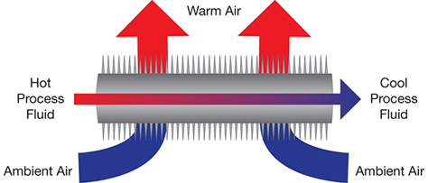
▲Figure 1. In an air-cooled heat exchanger, hot process fluid flows through a finned tube. Ambient air passes over the finned tube, which cools the process fluid.
The operating principle of an ACHE is straightforward. Hot process fluid enters one end of the ACHE and flows through tubes, while ambient air flows over and between the tubes, which typically have externally finned surfaces (Figure 1). The process heat is transferred to the air, which cools the process fluid, and the heated air is discharged into the atmosphere. While this is a fundamentally simple concept, maintaining optimum ACHE performance takes diligence.
The sizes of these units vary widely, from the very small (e.g., a car or truck radiator) to the very large (e.g., an A-frame vacuum steam condenser). Therefore, optimization of existing ACHEs can take several approaches. For the purpose of this article, optimization will be limited to those ACHEs typically found in refineries, chemical plants, or power plants built to American Petroleum Institute (API) Standard 661 (1).
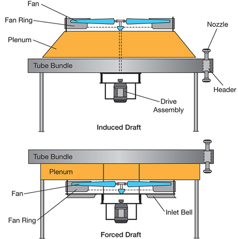
▲Figure 2. An air-cooled heat exchanger typically has one or more tube bundles, a fan, a plenum between the bundles and the fan, and a support structure high enough to allow air to enter at a reasonable flowrate (2).
There are two basic types of ACHEs found in petrochemical plants (Figure 2) (2):
- forced draft — the fan is located below the process bundle and air is forced through the tubes
- induced draft — the fan is located above the process bundle and air is pulled, or induced, through the tubes.
A typical ACHE has the following components (3):
- one or more bundles of heat-transfer surface consisting of finned or bare tubes connected by headers
- an air-moving device, such as an axial-flow fan, blower, or stack
- unless it is a natural draft application, a driver (usually an electric motor) and power transmission device (usually belt or gear) to mechanically rotate the air-moving device
- a plenum between the bundle(s) and the air-moving device
- a support structure high enough to allow air to enter beneath the ACHE at a reasonable flowrate
- optional header and fan maintenance walkways with ladders to grade
- optional louvers for process outlet temperature control
- optional recirculation ducts and chambers for protection against freezing or solidification of high-pour-point fluids in cold weather
- optional variable-pitch fan hub or variable-frequency drive for temperature control and power savings.
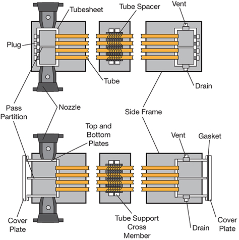
▲Figure 3. Tube bundles may be constructed with plug headers (top) or cover plate headers (bottom).
Headers distribute fluid from the source piping to the finned tubes. For most applications, a plug box header design is used for the tube bundle (Figure 3, top). A cover plate header design can be used if the inside of header boxes must be accessed (Figure 3, bottom). Although it is the more expensive alternative, the cover plate design allows full access to the inside of the headers for inspection and cleaning. The cover plate design is usually limited, however, to a maximum design pressure of 350 psig.

▲Figure 4. A winterized forced-draft unit is outfitted with methods to control the process fluid temperature leaving the ACHE.
A subset of the forced-draft design is the winterized unit (Figure 4). A forced-draft ACHE is outfitted with one or more methods (e.g., air outlet louvers, fans equipped with variable-frequency drives, hot air recirculation systems) to control the temperature of the process fluid leaving the exchanger. This type of unit is typically found in colder climates, but it is also used in hotter climates, such as the U.S. Gulf Coast, for process fluids with high viscosities and/or high pour points.
Routine maintenance
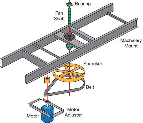
▲Figure 5. A typical mechanical drive system for an ACHE fan consists of an electric motor with a speed reducer such as a belt drive.
The reliability and thermal performance of any ACHE depends on how well its mechanical components are maintained. Figure 5 shows a typical ACHE mechanical drive layout. The components of ACHEs are fairly common; typically each bay has one, two, or three electric-motor-driven fans. Most have a speed reducer consisting of either a belt drive (e.g., V-belt or cog belt) or a right-angle gear drive.
A belt-drive system has four bearings that need to be lubricated — two motor bearings and two fan bearings for each fan. These are typically tubed to a common location somewhere on the drive assembly so they can be lubricated while the exchanger is running. Manufacturers usually recommend that you grease the bearings once a month if the coolers are in continuous operation. Right-angle gear drives should be lubricated according to the manufacturer’s recommendations.
Check belt tension on a regular basis, usually every six weeks at a minimum for ACHEs that are in continuous service. Check belts for wear, and sprockets for tooth wear or cracking.
Inspect fans at least annually by following these procedures (4):
- Visually inspect each blade and the hub, looking for cracking, rubbing, or excessive wear.
- Check all bolting hardware for proper torque, especially the blade-clamping bolts.
- Check blades for proper pitch as per the ACHE specification sheet. (Be sure to use the fan manufacturer’s blade angle procedure, as this can vary from one manufacturer to another.)
- Check the blade tracking to be sure that all blades are riding in the same plane in the fan ring.
- Check blade tip clearances to be sure that they are all within recommended limits.
Anti-rotation devices should be installed on fans to...
Would you like to access the complete CEP Article?
No problem. You just have to complete the following steps.
You have completed 0 of 2 steps.
-
Log in
You must be logged in to view this content. Log in now.
-
AIChE Membership
You must be an AIChE member to view this article. Join now.
Copyright Permissions
Would you like to reuse content from CEP Magazine? It’s easy to request permission to reuse content. Simply click here to connect instantly to licensing services, where you can choose from a list of options regarding how you would like to reuse the desired content and complete the transaction.