Sections
This analysis of the Bhopal gas tragedy reveals how to avoid introducing unnoticed hazards that can increase the risk of a runaway reaction.
This special three-part series commemorating the Bhopal gas tragedy’s 40th memorial began with the publication of Part I in September 2024, which explained how to develop an effective process safety culture (1). The second article, published in November 2024, highlighted the importance of eliminating common cause failures from process design (2).
This final article further develops the underlying themes involving workaround solutions and design dependencies to define how their interaction produced the hazards responsible for the Bhopal gas tragedy. Applying this knowledge improves our ability to prevent runaway reactions in modern industrial processes.
Introduction
The original “Bhopal Methyl Isocyanate Incident Investigation Team Report,” published by Union Carbide Corporation (UCC) in 1985, serves as the primary reference for the first two articles in this series (3). However, the original 1985 report is not the only investigation report issued by UCC. In 1988, UCC released a technical paper entitled “Investigation of Large-Magnitude Incidents: Bhopal as a Case Study” with the engineering consulting firm Arthur D. Little, Inc. (4). UCC used this platform to communicate additional information that became available after the 1985 report was published. While the original 1985 report is no longer actively distributed, the follow-up 1988 report can be freely downloaded from www.bhopal.com, UCC’s official website for dispensing information about the Bhopal gas tragedy. Reviewing information from the 1988 report promotes a better understanding of the events that led to history’s worst industrial disaster.
Design specifications
The methyl isocyanate (MIC) storage tank diagram (Figure 1) designates how tank vapor was handled under both normal and emergency situations (3). Two separate vent lines were connected to each tank, which delivered tank gas into the vent gas scrubber (VGS) and flare tower for destruction. Under steady-state operation at 2 psig (1.14 atm), low-pressure MIC storage tank headspace vapor vented into the scrubber through the process vent header (PVH) connection, which was normally kept open. If the tank pressure rose above 40 psig (3.7 atm), it was considered an emergency situation, and a safety valve would automatically open to route MIC gas into the flare tower through the relief valve vent header (RVVH). This safety precaution mitigated leak and explosion hazards that could result from exceeding the 60 psig (5.1 atm) MIC storage tank hydrostatic test pressure.
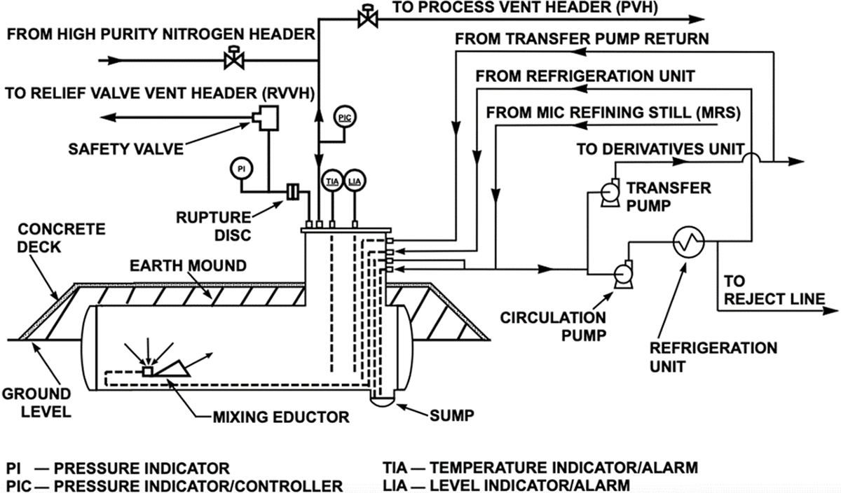
▲Figure 1. The methyl isocyanate (MIC) storage tanks were designed to vent from two locations: the process vent header (PVH) and relief valve vent header (RVVH). A nitrogen purge system continuously swept MIC storage tank headspace gas into the process vent header for destruction in the scrubber tower (3).
UCC design standards specified stainless steel as an approved material for constructing equipment in MIC service (3). Stainless steel resists rust formation, making it compatible with MIC (5). Lower-quality materials were not approved for MIC service due to their lack of rust resistance. Carbon steel, for example, corrodes upon contact with moist air to form a surface layer of rust. This must be avoided since, in the presence of MIC, rust acts as a catalyst for an undesirable side reaction that forms a nuisance material commonly called MIC-trimer (Figure 2). MIC-trimer is a polymeric compound with a high melting point (178°C) that clogs pipes and prevents closed valves from sealing properly (5). Thus, the best way to avoid MIC-trimer buildup in pipes and valves was to construct any equipment operating in MIC liquid or gas service with stainless steel in adherence to UCC’s design standard.
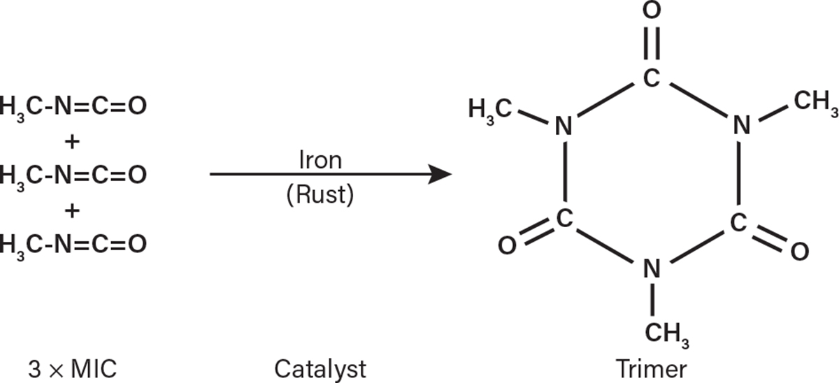
▲Figure 2. Metallic oxides like rust act as a catalyst for MIC to polymerize into MIC-trimer. Therefore, carbon steel was not approved for use in MIC service (3).
In full conformance with MIC process design specifications, UCC’s preexisting MIC process in the U.S. was constructed entirely with stainless steel. However, in the interest of cost savings, the Bhopal factory’s MIC storage tank vent header piping and valve metallurgies were downgraded and substituted with carbon steel (6). Since MIC vapor could flow into the process vent header and relief valve vent header at any moment, it could be catalyzed by the rust formed on the carbon steel cavities and, as a result, clog the MIC storage tank vent lines with MIC-trimer.
Nonconformance hazard
Figure 1 shows an incoming tank connection from the MIC refining still (MRS). This distillation column is where MIC product was separated from its organic chloroform (CHCl3) solvent. Pure distilled MIC product leaving the refining still was piped directly into either Tank 610 or Tank 611 for intermediate storage. The storage tank level would rise as it filled, displacing a corresponding volume of MIC tank vapor into the carbon steel vent header. Displaced tank headspace vapor was then routed into the scrubber, which ultimately discharged clean (MIC-free) tank vapor into the atmosphere.
Forming MIC-trimer inside the narrow, 2-in.-dia. (5-cm.-dia.) process vent header would produce backpressure on the refining still as the tank was filling. This could cause flooding in the refining still (3), which would send chloroform overhead with the distilled MIC product. The resulting storage tank contamination could lead to exceeding the maximum chloroform impurity limit in the MIC storage tank (3). Under these conditions, the MIC storage tank contents would have to be reprocessed or destroyed, causing considerable economic loss along with possible production delays. To prevent these unnecessary system performance issues, constructing the vent headers according to the UCC design specification would have been the inherently clean design solution.
If carbon steel were used, one workaround to the problem of MIC-trimer formation would involve flushing the affected equipment with water. It is important to note that introducing water to a process containing reactive MIC could cause unintended contamination, leading to a thermal runaway reaction. Therefore, considering the safety and economic disadvantages related to this decision, there appears to be no valid argument for deviating from the approved stainless steel design standard. Regardless, Union Carbide India Limited (UCIL) constructed the vent system with carbon steel. A closer review of the original MIC storage system design explains what made this variance acceptable.
Value engineering in major capital projects
A basis for downgrading the vent header metallurgy to less-costly carbon steel originates within the principles of value engineering (7) as it relates to the Bhopal factory’s MIC storage tank design. Value engineering is a capital project process that analyzes the design features, systems, equipment, and material selections to achieve essential product functionalities at reduced lifecycle costs. Its purpose is to consider design alternatives to optimize the expected cost-to-value ratio without compromising performance, quality, reliability, or safety. However, cases like the Grenfell Tower fire on June 14, 2017 (Figure 3) are a sobering reminder of how value engineering benefits can be defeated if proper caution is not exercised during the analysis (8).

▲Figure 3. The Grenfell Tower fire resulted in catastrophic loss of life and property in 2017. During a building renovation project two years earlier, the building’s cladding was replaced with materials that were less expensive than the original cladding, which reduced the structure’s fire resistance. Image courtesy of Natalie Oxford (2017).
In the Grenfell Tower incident, the original zinc cladding material that covered a 24-story residential building in the U.K. was downgraded to a plastic-filled aluminum composite material (ACM). Downgrading the cladding material reduced construction costs for a renovation project that was completed in 2016. However, replacing the original zinc cladding material with ACM reduced the building’s flammability resistance, causing disastrous consequences. Similarly, the vent header system’s inherent corrosion resistance was lost by downgrading its construction materials at the Bhopal factory.
The MIC storage tank diagram (Figure 1) shows that each MIC storage tank was equipped with a continuous nitrogen purge. The nitrogen purge prevented the accidental ignition of the tank’s flammable contents by eliminating air from its headspace. Since nitrogen flow into the tank could be unintentionally interrupted, introducing an ignition hazard, the following measures were taken to mitigate risk (3): “The nitrogen supply is protected with a bank of 450 cylinders of nitrogen at the supplier’s plant adjacent to the UCIL plant. The header in the MIC facility also has an alarm to indicate low nitrogen pressure. This alarm is to alert the operators to take corrective action to prevent possible contamination.”
The nitrogen sweep was designed to hold the MIC storage tank pressure at a maximum pressure of 2 psig (1.14 atm) during all phases of operation (Figure 4). These phases included filling the tank, transferring material out of the tank, and maintaining the tank in standby mode when no filling or transferring operations were in progress. Nitrogen flow was automatically regulated by a set of pressure control valves. Maintaining a constant flow of nitrogen through the vent valves created an inert environment from the carbon steel vent header to the scrubber. Under these design conditions, neither rust nor MIC-trimer could form on the internal MIC tank vent pipe and valve surfaces, keeping them clean and reliable. Accordingly, UCIL engineers downgraded the tank venting system metallurgy to carbon steel to “optimize” MIC process installation costs.
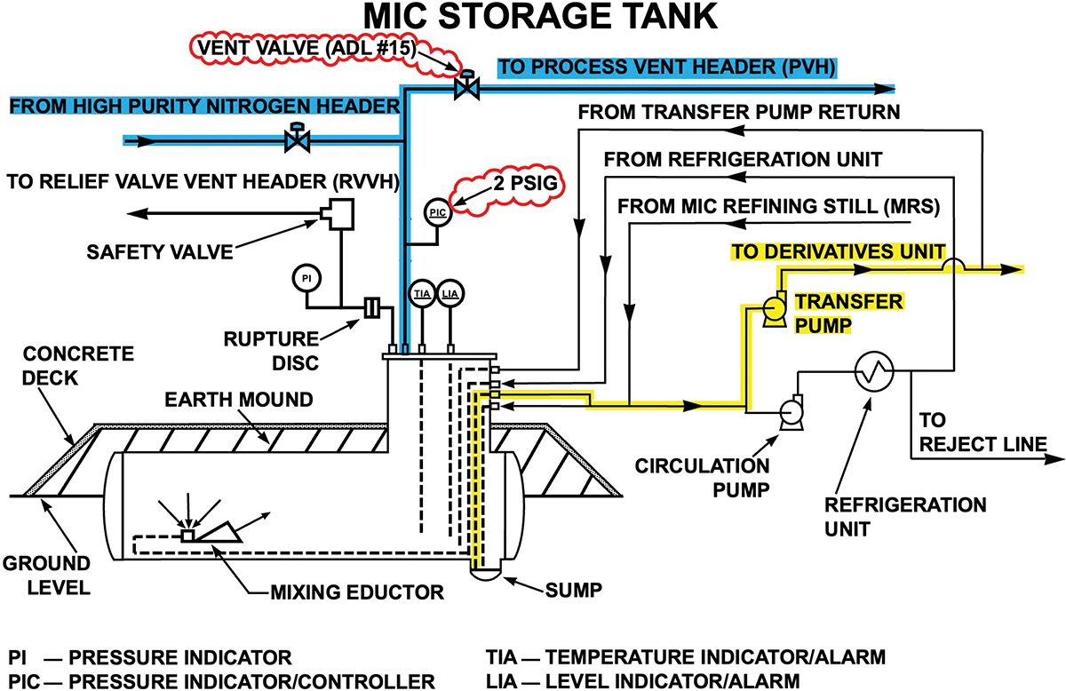
▲Figure 4. The value engineering basis for carbon steel MIC storage tank vent lines was dependent on using transfer pumps as prescribed in the original design. The carbon steel vent lines protected by nitrogen are highlighted in blue, while the design basis transfer pump pathway at 2 psig (1.14 atm) tank pressure is highlighted in yellow. The tank’s normally open vent valve is marked ADL #15 (3, 4).
Management of change (MOC)
The MIC transfer pump (Figure 4) was needed to move MIC into the SEVIN (the brand’s carbaryl pesticide) unit for pesticide production since the storage tank was designed to always operate slightly above atmospheric pressure. Using the transfer pumps as intended by design minimized the need for operator interaction, which in turn prevented human factors from interfering with process operation. Moving MIC into the SEVIN unit simply required opening or closing a valve on the corresponding transfer pump discharge line.
Shortly after the MIC unit began operating at the Bhopal factory, a change was introduced that significantly increased the likelihood of human error affecting system performance. This change involved using differential pressure to push MIC into the SEVIN unit for pesticide production without pumps (Figure 5), presumably to overcome reliability issues, as experienced by the circulation pumps (1, 2). The 1988 report summarizes how the nitrogen purge system provided the motive force to send MIC into the pesticide reactors without the transfer pumps (4): “A nitrogen pressure of at least 14 psig in the MIC storage tank was necessary to move the material from the storage area to the SEVIN unit charge pot at a reasonable rate.”
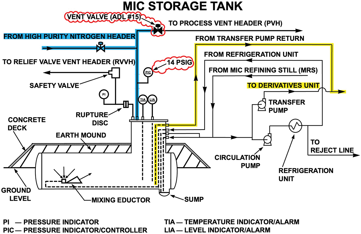
▲Figure 5. A workaround MIC transfer method was introduced to replace the failing transfer pumps. This change required closing the vent valve (marked ADL #15), contrary to the design basis. Nitrogen (highlighted in blue) could then be used to raise the tank’s pressure to 14 psig (1.95 atm), which made it possible to send MIC through the alternative pathway (highlighted in yellow).
The substitute MIC transfer method required switching the vent valve from automatic to manual control. Console operators were to open the vent valve when filling the tank and close it at all other times to establish 14 psig (1.95 atm). However, closing the vent valves interrupted the constant flow of nitrogen that prevented moist air from entering the carbon steel vent header system. As a result, rust formed on the internal MIC tank vent pipe and valve surfaces.
After implementing this change, MIC in the displaced headspace gas contacted the rusted vent header pipes and valves while the tank was filling. A water washing procedure was introduced as an alternative solution to remove the resulting MIC-trimer, which avoided possible product quality issues and business interruption. Whereas previously, a leaking vent valve created no observable safety or production impact, the new pumpless transfer method required keeping the carbon steel vent valve as clean as possible. Failure to do so could result in inadequate storage tank isolation, making it impossible to transfer MIC into the pesticide reactors.
Abandoning the MIC transfer pumps in exchange for nitrogen pressure introduced the hazard of a runaway reaction inside a storage tank. Prior to implementing this change, there was no need to regularly flush MIC process equipment with water. The water washing procedure was an administrative, human-dependent workaround solution that kept the carbon steel pipes and valves clean after interrupting continuous nitrogen flow through the vent header system. As a result, it defeated the preexisting value engineering benefit by adding equipment lifecycle costs while also introducing the hazard of a runaway reaction from MIC contamination.
MIC transfer failure
Legal documents confirm that an excessive amount of MIC-trimer was present in the vent header system when the runaway reaction inside Tank 610 occurred. Regarding the carbon steel vent headers, court proceedings from the district of Bhopal disclosed that: “The pipelines were corroded, choked, and valves were leaking” (9). Facts contained in the 1985 report indicate that MIC-trimer had deposited inside Tank 610’s vent line and valves while the last batch of MIC was being loaded into the tank. This explanation corresponds with information in the 1985 report that verifies the refining still was flooding while filling Tank 610, as would be expected when operating with “choked” tank vapor vent lines (3). The 1985 report stated: “The chloroform content of the MIC left in the MRS product line was between 12 and 16 percent, as reflected in samples taken and analyzed on December 16. This indicates that the last product from the MRS to Tank 610 contained well over the specification maximum of 0.5 percent chloroform.”
A sketch included in the 1988 report (Figure 6) details the orientation of Tank 610’s vent valve (Item #15) relative to the common valve (Item #16). The carbon steel common valve was the material specification break location and primary isolation point between the stainless steel MIC storage tank and the carbon steel process vent header system manifold. Considering the reported condition of carbon steel components in the MIC service, MIC-trimer buildup inside the vent valve likely made it impossible to isolate Tank 610. Both the 1985 and 1988 reports point to this explanation as the probable cause behind why MIC could not be transferred out of Tank 610 before the toxic gas release occurred. Under these circumstances, restoring production from Tank 610 would first require cleaning the vent valve.
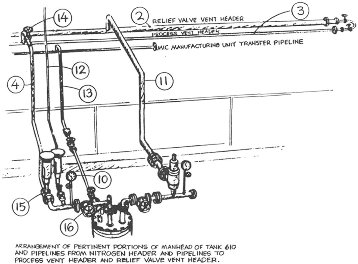
▲Figure 6. A sketch of Tank 610’s head manifold (4) shows the orientation of the carbon steel vent valve (Item #15) and carbon steel common valve (Item #16). The presence of MIC-trimer inside the vent valve at the end of the MIC production run on Oct. 22, 1984 made it impossible to use the MIC stored in Tank 610 for pesticide production.
Conclusions
This analysis illustrates how hazards that increase the risk of a runaway reaction can originate with good intentions directed at improving plant safety, equipment, economic, and processing performance. The Bhopal factory case study shows how a process can become incrementally less stable as multiple competing layers of workaround solutions and system dependencies become more prevalent. Individually, these creative steps may appear to solve an immediate problem, but the hidden consequences related to the complex interweaving of multiple singular improvement changes can be disastrous.
Combining the information provided in UCC’s 1985 and 1988 investigation reports clarifies specific actions that elevated the risk of a thermal runaway reaction inside an MIC storage tank. Beginning with the first article, we see how the Bhopal factory’s process safety culture was tuned to rely on workaround solutions; it was even suggested that a workaround solution was the proper way to address loss of MIC refrigeration.
This theme integrates with the last two articles, explaining how workaround solutions can raise the risk of a runaway reaction by breaking old, or creating new, system dependencies. For example, the nitrogen purge system was originally designed to prevent igniting stored MIC. However, doubling its use as a corrosion inhibitor made it possible to downgrade the vapor vent header piping to carbon steel while creating a permanent dependency on continuous nitrogen flow. The nitrogen purge system’s function was further redefined to create a workaround solution for MIC transfer pump failures, which sacrificed its expanded corrosion inhibitor function. The resulting carbon steel vent system corrosion could not be avoided, so its impact was managed by routine water washing to remove MIC-trimer deposits. Abandoning the MIC transfer pumps created a new common cause failure mechanism involving the storage tank vent valves. After these design changes, pesticide production required a clean vent valve to successfully implement a procedure that, ironically, made the system unclean due to the resulting buildup of MIC-trimer on carbon steel components in MIC service. Furthermore, flushing affected carbon steel materials with water required meticulous process isolation to ensure process and public safety, whereas previously, the use of water — which could trigger a runaway reaction — was both unnecessary and absent.
India’s Council of Scientific and Industrial Research (CSIR) unraveled this tangled web of cause-and-effect in their 1985 report on the toxic gas release. The report coherently expresses the changes’ combined impact over a six-week period that ended on the night of the runaway reaction (6): “Trimerisation of MIC to solid material in small quantities and consequent choking of lines leading to tank was a frequent occurence [sic] and seems to have been well accepted by the plant operating staff. Similarly, cleaning and purging with water of lines associated with the storage tanks was also accepted as a routine procedure. The hazards presented by ingress of water or other contaminants which could cause trimerisation and lead to choking was not appreciated and the Tank 610 was allowed to stay without positive nitrogen pressure from 22nd October to 2nd December, 1984.”
Managing the problem referenced in the CSIR report required cleaning Tank 610’s vent valve. Considering the condition of the vent valve as described in this article, it is likely that Tank 610’s carbon steel “common valve” (Figure 6, Item #16) was also leaking for the same reason. In that case, any attempt to restore pesticide production from Tank 610 by directly flushing the vent valve with water would have initiated the contamination incident that resulted in the runaway reaction. Preventing a similar sequence of events that could end with a runaway reaction in today’s industrial processes therefore requires:
- taking time to consider the full picture when making any incremental change, regardless of how minor it might appear
- exercising extreme caution when managing changes to improve safety to avoid a false sense of security that elevates existing or creates new hazards
- always selecting the inherently clean or inherently safe design solution when considering options for mitigating process risks
- developing an appetite for case studies like the one documented here to instill a hazard awareness that adds value when you detect similar situations in your processes
- meticulously isolating inventoried process equipment before performing maintenance where contamination hazards exist
- only accepting workaround solutions through a rigorous MOC process that considers how to address additional risks, avoids creating new (or breaking existing) system dependencies, and eliminates additional human factor issues.
In the interest of your responsibility to protect yourself and the lives of others, may your pursuit of process safety be guided by what you have learned about the Bhopal gas tragedy.
Literature Cited
- Bloch, K., and B. K. Vaughen, “The Bhopal Gas Tragedy — Part I: Process Safety Culture,” Chemical Engineering Progress, 120 (9), pp. 23–28 (Sept. 2024).
- Bloch, K., and B. K. Vaughen, “The Bhopal Gas Tragedy — Part II: Pumps,” Chemical Engineering Progress, 120 (11), pp. 48–53 (Nov. 2024).
- Union Carbide Corporation (UCC), “Bhopal Methyl Isocyanate Incident Investigation Team Report,” Danbury, CT, pp. 35–70, https://nepis.epa.gov/Exe/ZyPURL.cgi?Dockey=2000W9PM.TXT (Mar. 20, 1985).
- Kalelkar, A. S., “Investigation of Large-Magnitude Incidents: Bhopal as a Case Study,” presented at the Institution of Chemical Engineers Conference on Preventing Major Chemical Accidents, London, England, https://www.bhopal.com/document/case-study.pdf (May 10–12, 1988).
- D’Silva, T., “The Black Box of Bhopal: A Closer Look at the World’s Deadliest Industrial Disaster,” Trafford Publishing, Bloomington, IN (2008).
- Varadarajan, S., et al., “Report on Scientific Studies on the Factors Related to Bhopal Toxic Gas Leakage,” https://bhopalgasdisaster.wordpress.com (Dec. 1985).
- U.S. General Services Administration, “Value Engineering,” https://www.gsa.gov/real-estate/design-and-construction/engineering/value-engineering, GSA, Washington, DC (2024).
- Ministry of Housing, Communities & Local Government, “Independent Review of Building Regulations and Fire Safety: Final Report,” https://www.gov.uk/government/collections/independent-review-of-building-regulations-and-fire-safety-hackitt-review, MHCLG, London, UK (2018).
- District Court of Bhopal, India, “State of Madhya Pradesh Through CBI vs. Warren Anderson & Others,” Criminal Case No. 8460 of 1996, https://www.ielrc.org/content/c1004.pdf, (2010).

Copyright Permissions
Would you like to reuse content from CEP Magazine? It’s easy to request permission to reuse content. Simply click here to connect instantly to licensing services, where you can choose from a list of options regarding how you would like to reuse the desired content and complete the transaction.
