
Sections
Ultrasonic flowmeters use sound waves to calculate fluid velocity, offering versatile flow measurement of challenging fluids such as flare gases.
The chemical process industries (CPI) rely on accurate measurement of gas flows through piping to optimize efficiency, reduce emissions, and increase profits. Depending on the phase of the medium, several types of flowmeters are available, such as Coriolis mass flowmeters, thermal meters, and volumetric flowmeters, among others. Each type of flowmeter uses different physical, mechanical, and electrical principles to measure flow to suit application requirements. Choosing the right flowmeter for your installation and principle of measurement depends on the phase of the medium, process conditions (e.g., temperature, pressure, velocity), and measurement objectives (e.g., level of accuracy).
Measuring the volumes of gas expelled through flare systems is one of the more challenging forms of gas flow measurement. Flare gas is subject to wildly fluctuating velocity ranges, variable and extreme temperatures, and mixed compositions, which can hinder measurement accuracy. Among technologies that are currently available, ultrasonic gas flowmeters are typically the most suitable for measuring flare gas because they can handle variable conditions and operate accurately and reliably in harsh conditions.
This article explores the working principle of ultrasound and how it is used to measure the volume of flare gas flowing through a pipe.
Ultrasonic flowmeters
Ultrasonic flowmeters are the most common volumetric flow measurement device. Many different types of ultrasonic flowmeters are available, including:
- Transit-time flowmeters. This is the most widely used and advanced state-of-the-art measurement technology. We’ll be discussing this type of meter in this article.
- Doppler flowmeters. This is a popular and less-expensive flowmeter that uses the Doppler frequency shift. They are not considered as accurate as transit-time flowmeters and are viewed as complementary rather than competitive to transit-time flowmeters.
- Cross-correlation flowmeters. This flowmeter measures the energy absorption of the ultrasonic signal from two measuring sections installed with a certain distance between each other. A cross-correlation calculates the flow velocity.
- Phase-shift flowmeters. This flowmeter measures the phase position of the transmitting and receiving signal in the direction of the flow and against it. The resulting phase-shift angle is directly proportional to the flow velocity.
- Drift flowmeters. This flowmeter measures the attenuation of ultrasonic signals drifting across gas flow.
Principles of operation
Ultrasonic flowmeters rely on several physical, mechanical, and electrical principles to accurately measure gas flowrate over various conditions.
Physical principles. In general, when gas flows through a pipe, it flows in one direction at a velocity that is influenced by physical factors such as pressure and temperature, as well as the size of the pipe. For example, increasing the gas temperature causes it to flow faster. Similarly, increasing the pressure at one point in a pipeline will cause the gas to flow at a higher rate and velocity, which is why differential pressure is such a useful flow measurement.
Electrical principles. Sound waves can be generated by applying an electric charge to the surface of solid materials such as crystals and ceramics. This is known as the piezoelectric principle. In ultrasonic transducers, an oscillating electric current is applied to a ceramic crystal called the piezoelectric crystal. The crystal deforms naturally when an electric current is applied to it. By rapidly changing the electrical current, the crystal bends in one direction and then bounces back in the opposite direction, generating high-frequency bidirectional sound waves.
Mechanical principles. Sound waves are vibrations in the air that can move with or against the gas flow. The vibrations (mechanical oscillations) travel from molecule to molecule, thereby allowing the sound wave to travel through gas in any direction.
To better understand this principle, consider the honking of a car horn. The honking sound is generated by a rapidly vibrating diaphragm that transmits sound waves through the air (gas) from molecule to molecule. We can hear these sound waves because they vibrate at a high frequency in the audible range for humans (20 Hz to 20,000 Hz). Ultrasonic flowmeters operate at vibration frequencies outside of the audible range at 25 kHz or above. These higher frequencies allow for more accurate measurement and prevent noise pollution.
Components of an ultrasonic transducer
Ultrasonic transducers are sensors that are mounted and welded onto the flare pipe at carefully selected angles, positioned with specially designed piping mounts (Figure 1).
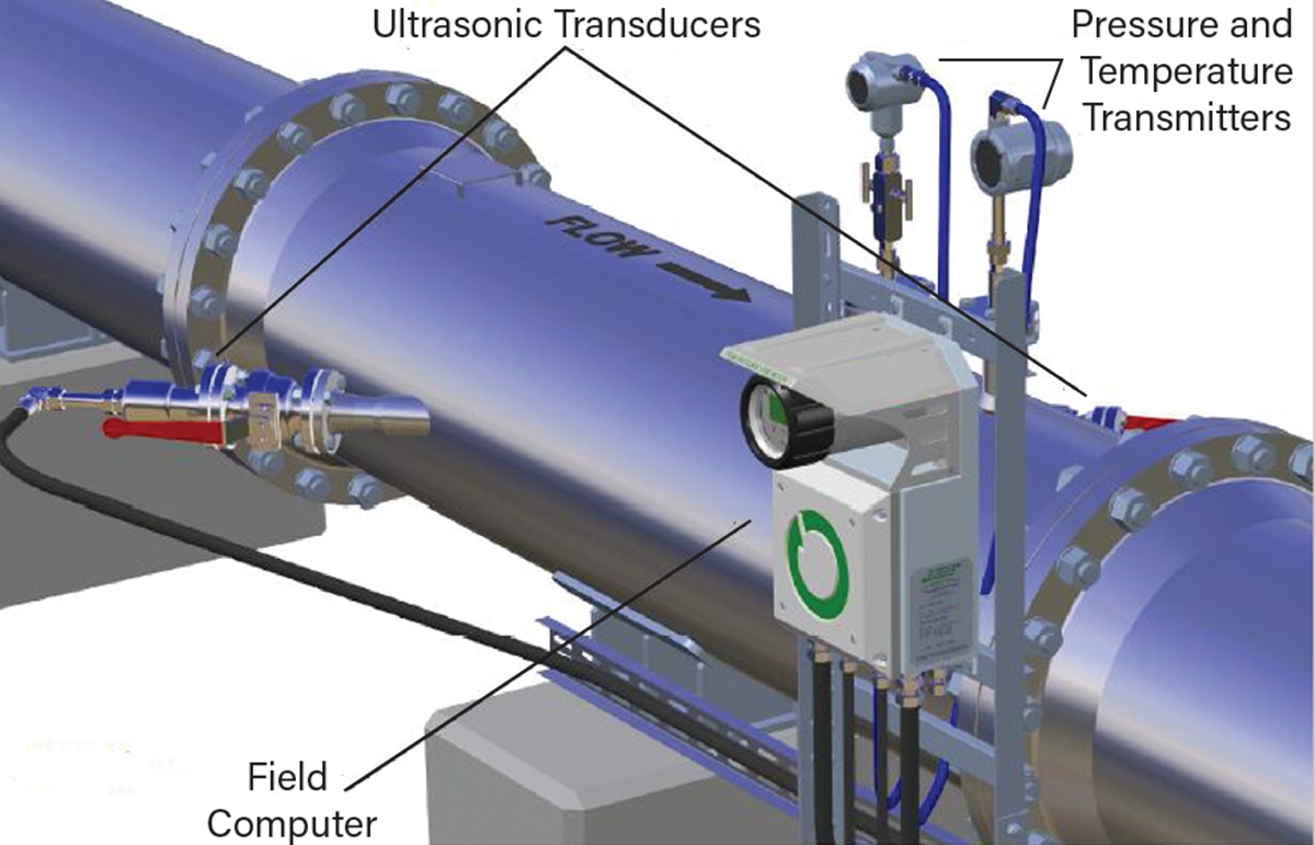
▲Figure 1. Ultrasonic transducers are mounted in sensor holders that are welded onto the flare pipe at carefully selected angles, positioned with specially designed mounts.
When the piezoelectric crystal, housed within a titanium membrane at the front of the transducer, is subjected to an alternating electric signal, both the crystal and the titanium membrane vibrate with the same frequency as the electric signal and generate ultrasonic signals. Since the crystal’s movement is bidirectional, the titanium membrane vibrates when a sensor receives ultrasonic signals, and the crystal converts this movement into an electric signal.
Both sensors operate in a pair as transmitter and receiver. At the transmitting sensor, an electrical frequency signal is converted to an ultrasonic pulse. At the receiving sensor, the signal is converted back to an electrical frequency signal, enabling the system to determine the time of travel for the ultrasonic pulse by measuring the difference in transit time. The differential transit time is used to calculate the axial gas flow velocity and volumetric flowrate in the pipeline.
Ultrasonic differential transit time
To illustrate differential transit time, consider two boats crossing a river diagonally on the same line: one in the current’s direction (flow) and the other against it (Figure 2). The boat moving in the direction of the flow takes considerably less time to reach the other riverbank than the boat moving against the direction of the flow. If we replace the river with gas flowing through a pipe and the boats with two sets of ultrasonic signals, we can see that ultrasonic waves along the diagonal path behave in the same way, as a sound wave propagates in the direction of the gas flow much more quickly than a sound wave propagating against the flow of the gas.
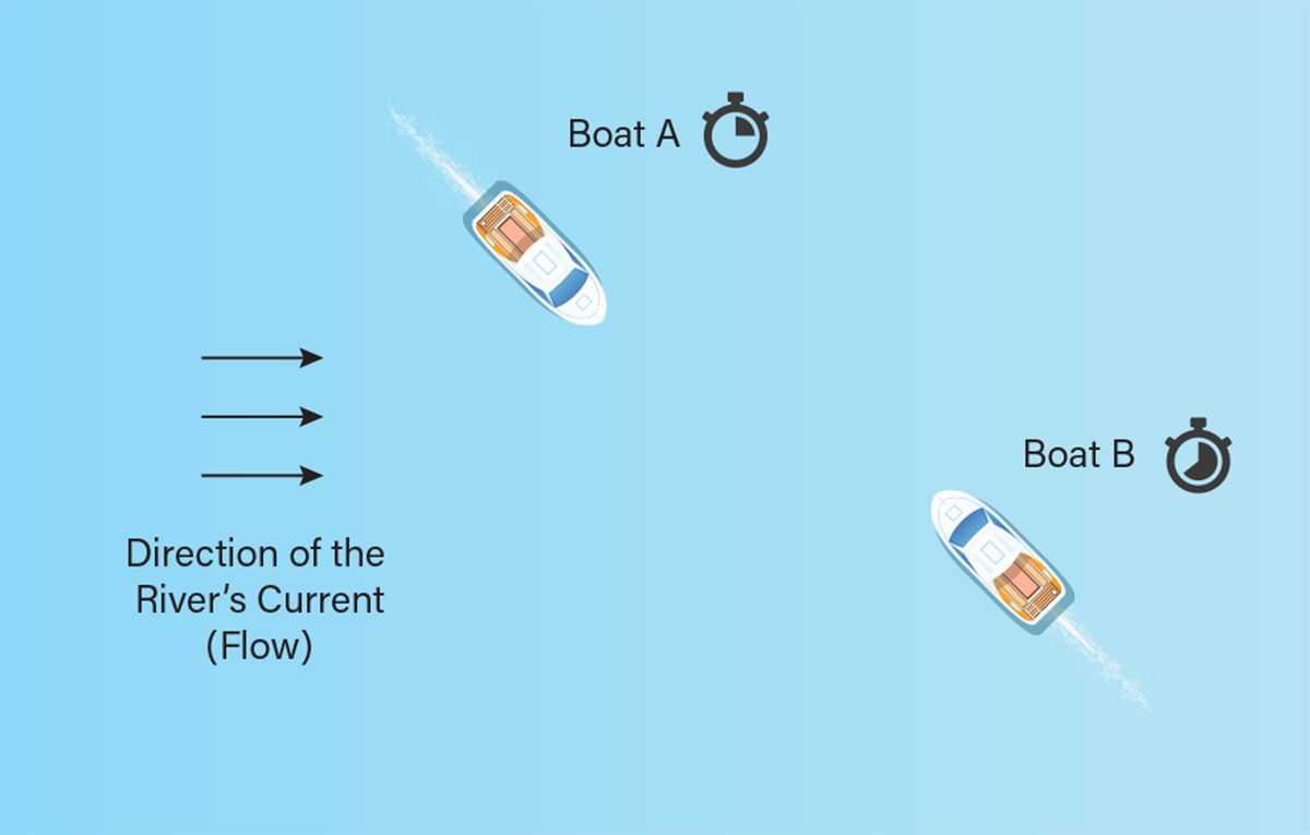
▲Figure 2. The principle of differential transit time can be illustrated with boats on a river. If two boats cross a river diagonally on the same line, one in the current’s direction (flow) and the other against it, the boat moving in the direction of the flow takes considerably less time to reach the other riverbank than the boat moving against the direction of the flow. Ultrasonic waves in a process pipe behave in the same way. A sound wave propagates in the direction of the gas flow much more quickly than a sound wave propagating against the flow of the gas.
The difference between the time it takes the ultrasonic signals to travel with and against the gas flow is referred to as differential transit time, and it is directly proportional to the flow velocity of the gas, i.e., the higher the gas flow velocity, the higher the differential time will be. Knowing this, we can calculate the gas volume and several other pieces of information about the gas.
In a process environment, ultrasonic transducers, always in pairs, are placed at an angle on opposite sides of a pipe, usually at 45 deg. A pair of transducers transmit and receive ultrasonic pulses along an acoustic path to measure the difference in transit time between the downstream pulse (from A to B) and the upstream pulse (from B to A) (Figure 3). The two transit times are then used to calculate the velocity of the gas flow using the following equation:

where v is the axial velocity (m/sec) of flowing medium without compensation for Reynolds number variation, L is the distance (m) between sensor tips, θ is the angle of the intersensory center line to the pipe axis, tAB is the transit time (sec) from Sensor A to Sensor B (downstream), and tBA is the transit time (sec) from Sensor B to Sensor A (upstream).

▲Figure 3. A pair of transducers transmit and receive ultrasonic pulses along an acoustic path to measure the difference in transit time between the downstream pulse and upstream pulse. Then, the two transit times and other relevant parameters — length between transducers (L) and angle of transducers (θ) — are used to calculate the velocity of the gas flow.
Overview of measurement signals
Ultrasonic flowmeters analyze two different signal types to measure the differential transit time. The combination of these signals is what makes ultrasonic flowmeters suitable for flare gas measurement. The two signal types used are:

▲Figure 4. Continuous wave (CW) signal bursts have a steady frequency and amplitude.

▲Figure 5. This chirp signal has a fixed amplitude and varying frequency.
Continuous wave measurement. The CW signal has a constant frequency and amplitude. This is a general signal type used in ultrasonic instruments. When measuring flare gases at high velocities, the medium in the pipeline will generate significant acoustic noise. This acoustic noise may have equal or higher amplitude and frequencies than the CW signal, which makes detection difficult or even impossible.
Chirp measurement. Chirp signals have a unique, recognizable form characterized by the duration and varying signal frequency of the pulse emitted by the piezoelectric crystals inside the transducers. The chirp signal’s unique form makes it detectable through the acoustic noise induced by the flowing medium. Figure 5 illustrates a chirp signal with a varying frequency and a fixed amplitude.
Chirp signals are used in combination with CW signals for measuring flare gases at low velocities. At higher velocities, the instrument uses only chirp signals. The combination of chirp and CW at low velocities improves the accuracy of flare meter measurements. The Fluenta FGM160 flare gas meter, for example, uses both CW and chirp signals.
Variations to ultrasonic differential transit time principle
Ultrasonic transducers can be mounted on pipes in several different ways. In some configurations, both transducers are mounted perpendicular (bias-90) to the pipe with the tip of the transducers protruding into the pipe and encountering the flowing gas (Figure 6). In other configurations, the ultrasound transducers are clamped onto the exterior of the pipe.
▲Figure 6. In a bias-90 configuration, two transducers are mounted perpendicular to the pipe, with the tip of the transducers protruding into the pipe and encountering the flowing gas.
In bias-90 configurations, the soundwave pulses travels through the medium from one transducer to the other. In such models, the part of the transducers inserted into the pipe could be affected by fouling (wax, sand, sludge, debris, etc.) over time, causing the ultrasound signals to attenuate slightly. However, in the clamp-on model, the sound wave must travel through the pipe wall and the medium. The pipe wall will absorb some of the pulsed signals, making the measurement far less accurate. Clamp-on models are not suitable for flare gas measurement, especially because they are also affected by low pressure in larger pipes.
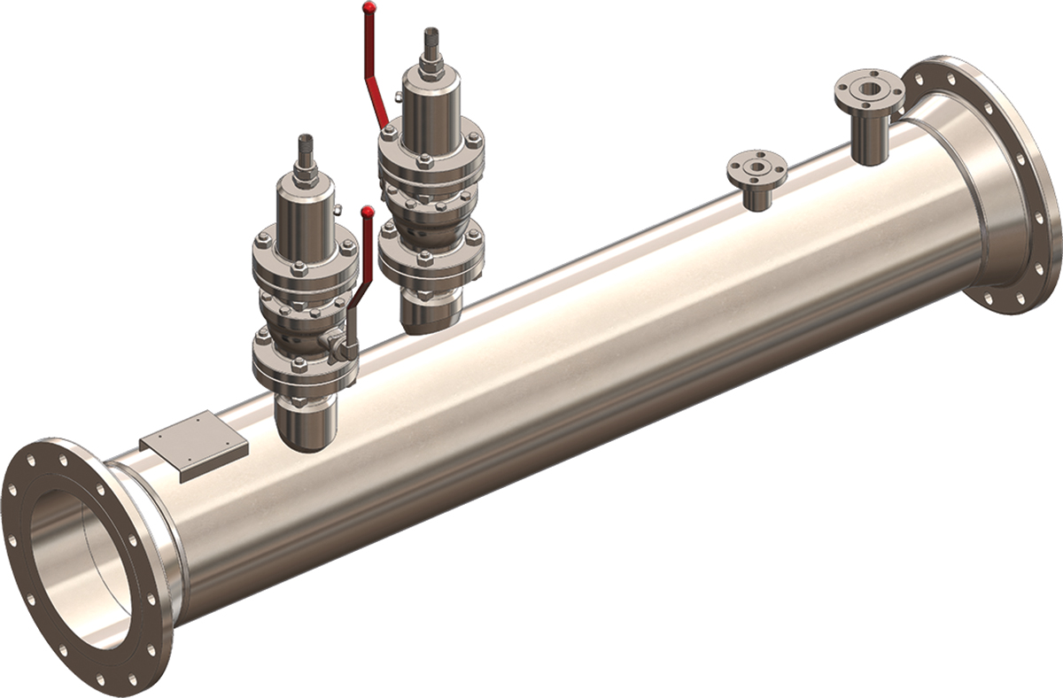
Ultrasonic transducers inserted at a 45-deg. angle are typically the most suitable setup. The transducers can be mounted in various configurations depending on available space and pipeline. For additional reassurance, two pairs of transducers (i.e., a dual-path configuration) can be used instead of a single pair for higher accuracy and redundancy (Figure 7). It is recommended to service the transducers yearly to avoid the attenuation of the transducers’ performance.
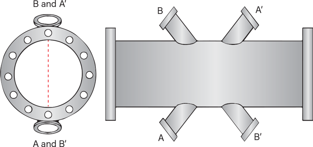
▲Figure 7. A dual-path flowmeter setup that uses cross-configuration improves measurement accuracy and redundancy.
Benefits of flare gas ultrasonic flowmeters
Flowmeter requirements vary depending on the application, but ultrasonic meters have become the go-to device for measuring flare gas. The wildly fluctuating velocity ranges, varying atmospheric conditions, extreme temperatures, and mixed gas compositions make measuring the volumes of natural gas expelled through flare systems one of the most challenging forms of gas flow measurement. Additional challenges arise in large pipes or applications that lack straight-run pipelines or have insufficient flow conditioning (e.g., offshore platforms).
Chemical and petrochemical facilities consider multiple technologies when looking to measure flare gas, including differential pressure, thermal mass, optical-photo, and ultrasonic technologies. Table 1 lists the advantages and disadvantages of these technologies and their suitability for flare gas applications.
| Table 1. When choosing a flowmeter for a flare gas application, certain technologies have different advantages and disadvantages. | ||
| Flowmeter Technology | Advantages | Disadvantages |
| Differential Pressure (DP) |
|
|
| Thermal Mass |
|
|
| Optical-Photo |
|
|
| Ultrasonic |
|
|
In the CPI, narrowing down the choice to the right technology is only half the battle, as the performance and features of ultrasonic flowmeters also vary depending on the manufacturer. Engineers must consider the technical suitability, reliability, and overall system compatibility when selecting a meter.
Temperature range and acoustic attenuation are often the primary considerations when selecting ultrasonic technology for flare gas. Acoustic attenuation is a function of the design and frequency of the transducer. Some flowmeters, such as the Fluenta FlarePhase, use a narrow band device with targeted frequencies and unique signal processing to minimize acoustic losses in difficult gases (e.g., CO2, methane) and ensure good performance. In addition, other technical aspects to consider include turndown ratio, velocity range, and pipe size capabilities.
In closing
Ultrasonic flowmeters are particularly suitable for processes handling the extreme cold and hot temperatures, low pressures, and high flow velocities found in applications such as natural gas pipelines, chemical plants, and oil and gas rigs. The versatile working principles of ultrasonic flowmeters make them one of the fastest-growing types of flowmeters. They enable operators to accurately measure the volume and velocity of products such as flare gas. Ultrasonic measurement devices are a useful way to ensure compliance with regulatory requirements concerning greenhouse gas emissions and meet environmental and performance goals.
Nomenclature
| L | = distance between sensor tips |
| tAB | = transit time (sec) from Sensor A to Sensor B (downstream) |
| tBA | = transit time (sec) from Sensor B to Sensor A (upstream) |
| v | = axial velocity of flowing medium without compensation for Reynolds number variation |
| Greek Letters | |
| θ | = angle of the intersensory center line to the pipe axis |

Copyright Permissions
Would you like to reuse content from CEP Magazine? It’s easy to request permission to reuse content. Simply click here to connect instantly to licensing services, where you can choose from a list of options regarding how you would like to reuse the desired content and complete the transaction.