
This article is based on a presentation at the 2019 AIChE Spring Meeting and 15th Global Congress on Process Safety, New Orleans, LA.
Low pressure does not mean low risk. If low-pressure tanks are compromised, they can release large volumes of material to the environment. Develop a safeguarding strategy for each tank at your site.
Low-pressure storage tanks abound in the chemical process industries (CPI) and are necessary to maintain a stable global supply of liquid raw materials, intermediates, and final products. These tanks enable storage of large quantities of material at low pressure, often in remote locations away from occupied buildings and public population centers. It is, however, irresponsible to assume that low pressure implies low risk.
While these storage tanks operate at low pressure, their large volumes pose greater risk than pressure vessels of smaller volumes. The maximum inventory of material that could be released in the event of loss of primary containment could produce dire consequences. In addition, relief of hazardous material to the atmosphere is a common component of their design, because the backpressure that could develop in a closed relief header often makes pressure relief via a closed system impractical. Inherently safer design with respect to equipment pressure and vacuum ratings is also generally not feasible for storage tanks, as it would require a pressure vessel, which would increase the cost of fabrication. A final risk is the sense of complacency that can develop around low-pressure tanks, particularly if they are sited in relatively remote locations.
Table 1 provides examples of process safety incidents involving low-pressure tanks in the U.S. over the past 20 years. Many of the incidents involved ignition of flammable material inside tanks caused by hot work in areas adjacent to those tanks — which emphasizes the risk of venting a low-pressure tank to atmosphere.
| Table 1. The U.S. Chemical Safety Board (CSB) completed investigations of these process safety incidents involving low-pressure tanks between 2000 and 2017 (1). | ||
| Date | Location | Description |
| Feb. 8, 2017 | DeRidder, LA | Flammable atmosphere in tank ignited by hot work 3 fatalities, 7 injuries |
| Oct. 21, 2016 | Atchison, KS | Incompatible material unloaded into incorrect tank caused a chemical reaction 120 medical treatment cases onsite and offsite |
| Jan. 9, 2014 | Charleston, WV | Chemical storage tank leak Contamination of municipal water supply |
| Nov. 9, 2010 | Buffalo, NY | Flammable atmosphere in tank ignited by hot work 1 fatality, 1 injury |
| Oct. 23, 2009 | Bayamón, Puerto Rico | Overfilling of gasoline storage tank caused fire and explosion Pressure wave and damage to approximately 300 homes and businesses up to 1.25 miles from site |
| Jan. 12, 2009 | Woods Cross, UT | Release of flammable vapor cloud from storage tank caused a flash fire Blast wave and damage to homes beyond the plant fenceline |
| Nov. 12, 2008 | Chesapeake, VA | Catastrophic fertilizer tank failure 2 injuries, community evacuation, contamination of public waterways |
| Oct. 11, 2008 | Petrolia, PA | Overfilling of acid storage tank Evacuation of approximately 2,500 members of the public ordered by first responders |
| July 29, 2008 | Tomahawk, WI | Flammable atmosphere in tank ignited by hot work 3 fatalities, 1 injury |
| June 5, 2006 | Raleigh, MS | Flammable atmosphere in tank ignited by hot work 3 fatalities, 1 injury |
| Jan. 11, 2006 | Daytona Beach, FL | Flammable atmosphere in tank ignited by hot work 2 fatalities, 1 injury |
| July 17, 2001 | Delaware City, DE | Flammable atmosphere in tank ignited by hot work 1 fatality, 8 injuries |
Effective design of low-pressure tanks requires consideration of the tank venting requirements for all credible causes of overpressure and vacuum and the implementation of appropriate safeguards for these scenarios. It is possible, and sometimes likely, that a low-pressure tank may require different types of safeguards for each individual credible overpressure or vacuum scenario. When designing these pressure- and vacuum-relief systems, it is important to understand the strengths and weaknesses of each safeguard, and to deploy these safeguards strategically to capitalize on their strengths and mitigate their weaknesses.
Tank overpressure and vacuum scenarios
API Standard 2000 defines the venting requirements for atmospheric and low-pressure storage tanks for both overpressure and vacuum. The standard covers causes of overpressure and vacuum, including additional scenarios to be considered for refrigerated tanks (Table 2) (2). Note that the causes of vacuum are often the inverse of analogous causes of overpressure.
| Table 2. API Standard 2000 includes possible causes of tank overpressure and vacuum (2). |
| Overpressure Causes |
| Liquid movement into a tank Weather changes causing temperature increase Fire exposure Pressure transfer vapor breakthrough Supply valves or regulators for inert pads or purges malfunction to the open position Abnormal heat transfer causing increased heating Internal failure of heat-transfer devices causing heating/cooling coil mechanical failure Vent treatment systems malfunction causing loss of vent flow Utility failure Increase in temperature of the input stream to a tank Exothermic chemical reactions Liquid overfill Control valve failure in the open position on the inlet or in the closed position on a vent Internal explosion/deflagration Mixing of products of different compositions |
| Refrigerated Tanks |
| Loss of refrigeration Heat input due to pump recirculation Evaporation due to ambient heat input Unexpected mixing of two liquid phases due to heat input, known as rollover Overpressure of the annular space of a double-wall tank |
| Vacuum Causes |
| Liquid movement out of tank Weather changes causing temperature decrease and/or precipitation Supply valves or regulators for inert pads or purges malfunction to the closed position Abnormal heat transfer increasing cooling Internal failure of heat-transfer devices causing cooling coil mechanical failure Vent treatment systems malfunction Utility failure Decrease in temperature of the input stream to a tank Endothermic chemical reactions Control valve failure in the closed position on the inlet Mixing of products of different composition |
| Refrigerated Tanks |
| Maximum refrigeration causing thermal contraction of liquid |
Overpressure scenarios fall into five general categories:
- liquid inflow caused by normal liquid flow to a tank or by unexpected diversion of liquid to a tank (e.g., liquid heat-transfer fluid ingress from a leak), which can displace the tank vapor space (i.e., outbreathing) or overfill the tank
- vapor inflow caused by the malfunction of a control valve or of a regulator on a tank blanketing system to the open position, breakthrough of pressurized motive gas used for liquid transfer, or mechanical failure of an internal steam heating coil or steam jacket
- change in heat transfer caused by high ambient temperatures or increased solar radiation, changes to process conditions upstream (e.g., hotter feed), an external fire, malfunction of a heating coil or jacket temperature control system, or loss of cooling or refrigeration system functionality
- loss of venting capacity caused by continuous tank-venting system malfunction to the closed position or plugging, or an intermittent tank-venting system that fails to open on demand
- mixing of incompatible materials caused by human error that generates exothermic reactions, deflagrations, or detonations.
Likewise, vacuum scenarios fall into four categories:
- liquid outflow caused by normal liquid effluent flow or unexpected diversion of liquid flow out of a tank (e.g., inadvertent opening of a normally closed drain valve) that pulls a vacuum on the tank vapor space (i.e., inbreathing)
- loss of vapor inflow caused by the malfunction of a control valve to the closed position or of a regulator on a tank blanketing system
- change in heat transfer caused by low ambient temperatures or decreased solar radiation, changes to process conditions upstream (e.g., colder feed), malfunction of a heating coil or jacket temperature control system, an increase in cooling or refrigeration system duty, or the introduction of cooling media directly into the tank in the event of a mechanical failure of a cooling coil or jacket
- mixing of incompatible materials caused by human error that generates endothermic reactions.
While API 2000 presents a fairly comprehensive list of causes of overpressure and vacuum, no code or standard can adequately address all conceivable processes. Therefore, it is incumbent upon those designing tank pressure- and vacuum-relief systems to seek and apply the knowledge and experience of engineering and operations personnel familiar with the process.
For example, one scenario not explicitly covered in API 2000 is vacuum due to a broken tank nozzle, possibly caused by vehicle impact (although this cause would likely fall under the liquid outflow category). The capacity for gravity-induced flow through a broken nozzle at the bottom of a tank could exceed the capacity of the pump used to move liquid out of the tank. The tank vacuum protection systems may be designed only for the pump-out rate, not the flow by gravity due to a broken nozzle, and this could cause a vacuum that exceeds the tank’s vacuum rating to develop (3). Personnel knowledgeable of the site should determine the likelihood of such a scenario by considering the location of the tank relative to vehicle traffic and other potential causes of nozzle damage.
Tank pressure- and vacuum-relief systems
Once the credible causes of overpressure and vacuum have been established for a tank, next consider the best strategy to safeguard against each of the scenarios identified. Various safeguards are available to do this and may be incorporated into the design of the tank or the surrounding process, included in the basic process control system (BPCS), or added as dedicated pressure- and/or vacuum-relief devices. Each of these types of safeguards has its own strengths and weaknesses (Table 3).
| Table 3. Strengths and weaknesses of tank overpressure and vacuum safeguards (2). | ||
| Safeguard | Strengths | Weaknesses |
| Overpressure | ||
| Free Vent to Atmosphere | Incorporated into tank design No moving parts | Tank vapor space is continuously open to atmosphere Vent elevation and/or discharge location may prevent proper relief of liquid overfill scenario |
| Flame/Detonation Arrestor Vent | Simple design similar to a free vent Prevents external ignition sources from igniting flammable vapors in tanks | Similar drawbacks to free vents Potential for plugging if not properly maintained Generally designed for temporary and/or localized ignition sources, but not a sustained fire |
| Overflow Line | Simple design similar to a free vent Can be routed to a closed system or designed with a liquid seal Effective for overfilling cases | Piping configuration may contribute to too much backpressure to provide effective vapor relief Potential static discharge if liquid is subjected to a significant free-fall distance Tank liquid level limited by overflow line nozzle location |
| Overflow Vent | Simple design similar to a free vent Effective for overfilling cases | Potential to generate significant flammable aerosols and vapors due to a waterfall effect Tank liquid level limited by overflow vent location |
| Continuous Venting via Pressure Regulator | Can be routed to a closed system Independent of basic process control system (BPCS) | Functionality can be compromised by high backpressure Regulator can malfunction (open or closed) if not properly maintained Regulator typically designed to vent vapor, and would not be effective for overfilling |
| Continuous Venting via Control Valve | Can be routed to a closed system Valve function can be observed remotely via human-machine interface (HMI) | Functionality can be compromised by high backpressure Susceptible to common-cause failure with other BPCS functions Control valve can malfunction (open or closed) if any part of the loop is not properly maintained Unlikely to be effective for liquid overfilling (similar to a regulator) |
| Reclosing Pressure Vent | Independent safeguard designed solely for pressure relief Keeps tanks isolated from atmosphere when not venting pressure | Can fail to function on demand if not properly maintained Not typically designed for liquid overfilling |
| Non-Reclosing Emergency Vent | Independent safeguard designed solely for pressure relief Can be fitted on a manway to provide significant relief capacity | Can fail to function on demand if not properly maintained Not typically designed for liquid overfilling If the vent opens due to a relief event or malfunction, the tank remains open to atmosphere |
| Vacuum | ||
| Free Vent to Atmosphere | Incorporated into tank design No moving parts | Tank vapor space is continuously open to atmosphere |
| Flame/Detonation Arrestor Vent | Simple design similar to a free vent Prevents external ignition sources from igniting flammable vapors in tanks | Similar drawbacks to free vents Potential for plugging if not properly maintained |
| Continuous Inert Blanketing via Pressure Regulator | Prevents air ingress from creating flammable mixture in tank vapor space Independent of the BPCS | Regulator can malfunction (open or closed) if not properly maintained Potential asphyxiation hazard if tank vapor space is vented to atmosphere |
| Continuous Inert Blanketing via Control Valve | Prevents air ingress from creating flammable mixture in tank vapor space Valve function could be observed remotely via HMI | Susceptible to common-cause failure with other BPCS functions Control valve can malfunction (open or closed) if any part of the loop is not properly maintained Potential asphyxiation hazard if tank vapor space is vented to atmosphere |
| Reclosing Vacuum Breaker | Independent safeguard designed solely for vacuum relief Keeps tanks isolated from atmosphere when not breaking vacuum | Can fail to function on demand if not properly maintained Air ingress to tanks when breaking vacuum could create a flammable internal atmosphere |
A tank overflow mitigation system can be installed on a tank with overflow vents to direct liquid flow via a closed gutter to secondary containment. This arrangement prevents the occurrence of cascading liquid (i.e., waterfall effect), which can increase the size of potential vapor clouds. A waterfall effect, such as occurred at an incident in Bayamón, Puerto Rico, on Oct. 23, 2009, can generate aerosols that can be ignited by an external ignition source or by static discharge from falling liquid. The waterfall effect can pose significant flash fire and vapor cloud explosion (VCE) hazards.
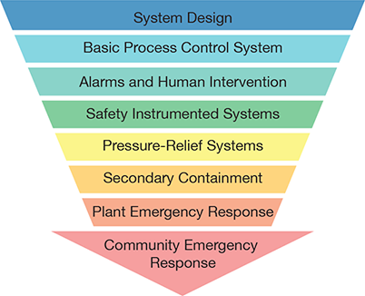
▲Figure 1. Low-pressure tanks and their associated processes should be designed to prevent overpressure or vacuum when practical. Beyond the design, the basic process control system (BPCS) can ensure stable operation. Alarms and human intervention may be appropriate if the BPCS is unable to maintain safe operation, which can be further backed up by safety instrumented systems, pressure-relief systems, secondary containment, plant emergency response, and community emergency response.
In addition to the strengths and weaknesses of the safeguards listed in Table 3, it is important to consider the hierarchy of controls (Figure 1). Protection of a tank against overpressure and vacuum by system design is the most desirable solution when possible.
System design. Safeguards should be considered for each level of the control hierarchy. Beginning with system design, changing the pressure or vacuum rating of a tank to achieve inherently safer design is often impractical; inherently safer design with respect to pressure rating may require a pressure vessel rather than a tank. Open atmospheric vents, flame and detonation arrestor vents, and liquid overflow lines may be considered as part of the system design, and their mechanical integrity must be ensured by an appropriate inspection, testing, and preventive maintenance (ITPM) program. Even with these safeguards in place and functioning, do not overlook the consequences of relief of hazardous tank contents to the atmosphere.
BPCS. Next, consider safeguards associated with the BPCS. Blanketing a tank with inert gas via the BPCS and/or mechanical pressure regulators can be an effective means of relieving pressure and breaking vacuum caused by liquid movement into or out of the tank. Such blanketing systems can eliminate the need to vent hazardous tank vapors to the atmosphere or pull air into the tank and potentially create a flammable internal atmosphere. However, blanketing systems may be a cause of overpressure and must be included in the ITPM program to ensure their continued functionality.
Alarms and human intervention. Safeguards related to alarms and human intervention might include a level alarm to prevent overfilling, which requires a sufficient response time from the initial alarm activation. Pressure alarms, however, generally do not allow sufficient response time before the tank pressure or vacuum rating is exceeded.
Safety instrumented systems. A safety instrumented system (SIS) may prevent overpressure or vacuum, but these systems require a high-integrity safety interlock independent of the BPCS, which necessitates significant investments in design, installation, maintenance, and testing. Consult engineering and operations personnel knowledgeable about the process associated with the tank and a SIS subject matter expert to verify the proposed system’s effectiveness for the application.
Pressure-relief systems. Tank pressure-relief systems, such as atmospheric pressure/vacuum conservation vents and emergency vent hatches, can be employed as safeguards. However, if the tank contains hazardous material, these types of safeguards should only be considered as a last line of defense against the malfunction of other safeguards in the hierarchy.
Secondary containment and emergency response. Secondary containment and emergency response, either on-site or in the surrounding community, are only intended to reduce the impact of a hazard created by the loss of primary containment. These types of controls should not be considered preventive safeguards.
Dispersion consequence modeling
Once the credible overpressure and vacuum scenarios are identified and a safeguarding strategy is developed, the next step is to evaluate the consequences of atmospheric dispersion of hazardous material releases from the tank’s relief devices.
Hazard assessment software can be used to conduct consequence modeling. To better understand this process, consider a hypothetical hexane storage tank at the Wilfred E. Baker Test facility in La Vernia, TX, with these specifications:
- length: 16 ft
- diameter: 4 ft
- orientation: horizontal
- head type: flat
- elevation above grade: 1 ft
- design pressure: 10 in. H2O(g)
Three overpressure scenarios were identified for the tank:
(a) liquid overfilling by a transfer pump with capacity of 100 gpm
(b) nitrogen blanket control valve malfunction to the open position based on a 50-psig nitrogen supply via a generic 1-in. globe valve
(c) external fire based on a liquid level of 75% of the tank diameter.
Each overpressure scenario has an associated safeguard:
(a) a 2-in. overflow line to grade for the overfilling scenario
(b) a 3-in. gooseneck vent (which would require a flame arrestor) for the nitrogen control valve malfunction
(c) an 8-in. emergency vent hatch for the external fire.
(Note that pressure and vacuum due to liquid movement into and out of the tank would also be vented via the 3-in. gooseneck vent, but those cases were not evaluated quantitatively for this example.)
Each dispersion scenario in Table 4 was modeled under two different weather conditions, F2.3 and D7.2. The letter in the name of the weather condition (i.e., F or D) represents the Pasquill atmospheric stability, where A represents the most unstable conditions and G extremely stable conditions; the number (i.e., 2.3 or 7.2) is the wind speed in meters per second. These weather conditions were chosen based on statistical meteorological data for the San Antonio International Airport (SAT) near the facility. The F2.3 weather conditions generated more significant consequences, so the discussion and figures present the results for those conditions.
| Table 4. Potential release sources for the hypothetical hexane storage tank modeled in the example. | ||||||
| Scenario | Material | Hole Diameter | Temperature | Pressure | Height of Release | Angle of Release |
| (a) Overfill | n-Hexane | 2 in. | 100°F | 0.361 psig | 1 ft | –90 deg. |
| (b) Control Malfunction | Nitrogen | 3 in. | 100°F | 0.255 psig | 5 ft | –90 deg. |
| (c) Fire | n-Hexane | 8 in. | 157.2°F | 0.218 psig | 5 ft | 90 deg. |
The software used to generate these images uses a free-field dispersion model that was developed based on one-dimensional turbulence theory (4). This model does not account for specific obstructions such as buildings; therefore, flammable clouds are reported up to 50% of the lower flammability limit (LFL). This generates a conservative illustration of areas where obstructions could create localized flammable mixtures in air.
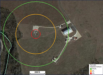
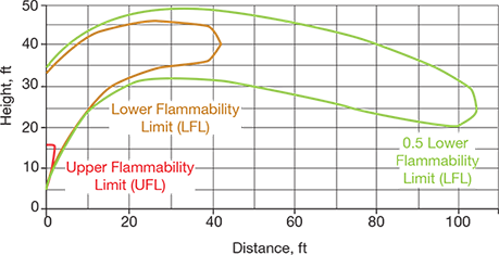
(a) Overfill scenario. Figure 2 shows the flammable vapor cloud contours for the relief of hexane via a 2-in. overflow line terminating 1 ft above grade. In this scenario, a flammable vapor cloud could extend up to hundreds of feet downwind of the release point and could affect an occupied building, but the cloud would remain within a 1.5-ft elevation above grade. Based on this model, it may be appropriate to add a preventive measure to the system, such as an interlock to shut down the transfer pump if the level in the tank is high, and/or add a means to mitigate the hazard, such as a properly sized secondary containment dike with appropriate hazardous area classification. The model shows the steady-state dispersion and does not account for exhausting the supply of hexane, which may be relevant depending on the quantity of hexane available upstream of the transfer pump (which was not defined for the purpose of this example).
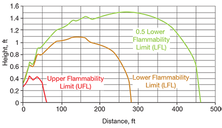
▲Figure 2. These plots illustrate the dispersion of a flammable vapor cloud generated by the overfilling of a hexane tank and relieved through a 2-in. overflow line terminating 1 ft above grade.
(b) Control malfunction scenario. The consequences of a release in the event the nitrogen blanket control valve malfunctions to the open position are different from those caused by the relief of hexane. Nitrogen is neither flammable nor toxic, but may pose an asphyxiation risk to personnel by creating a localized oxygen-deficient atmosphere. An atmospheric oxygen concentration of 20.9% is normal; levels of 19% can produce some adverse physiological effects, and levels below 10% can cause an inability to move, loss of consciousness, convulsions, and death (5).
Figure 3 shows the height and distance of an asphyxiation hazard cloud associated with the relief of the nitrogen control valve malfunction via a 3-in. gooseneck vent. The concentrations of oxygen in air are shown as 10%, 12.5%, and 14%. The maximum distance of the oxygen-deficient atmosphere is less than 1 ft, so the outdoor hazard is minimal. However, if the release point were located indoors and air circulation was limited by the building heating, ventilation, and air conditioning (HVAC) system, the oxygen concentration could drop to dangerous levels if the control valve malfunction went undetected.
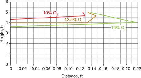
▲Figure 3. This plot displays the height and distance of an asphyxiation hazard caused by a release through a 3-in. gooseneck vent upon the malfunction of a nitrogen blanket control valve to the open position.
▲Figure 4. This plot displays the height and distance of a flammable vapor cloud generated by a release through an 8-in. emergency vent hatch on top of the tank in the event of an external fire.
(c) External fire scenario. Figure 4 shows the flammable vapor cloud for the relief of hexane via an 8-in. emergency vent hatch on top of the tank in the event of an external fire. The flammable cloud of vaporized hexane rises rapidly within the first 5 ft of horizontal distance from the release point; it then remains at least 20 ft above grade before dissipating and the concentration falls below the flammable range. This relief would not pose a hazard beyond the potential escalation of the fire due to the hexane vapor cloud. While this is not desired, it would still be preferable to a full rupture of the tank due to overpressure.
Had these three examples been part of an actual chemical plant pressure-relief dispersion study, plant personnel would have the option to pursue further risk analysis using more comprehensive methods, such as a site-wide facility siting study and/or a quantitative risk assessment (QRA).
Final thoughts
When evaluating the potential risks associated with overpressure and vacuum of low-pressure storage tanks, potential causes should be evaluated in accordance with API 2000. However, also consider scenarios not explicitly covered in this standard. Consult with engineering and operations personnel knowledgeable about tank locations relative to other equipment and activities, as well as of the process systems associated with the tanks. Evaluate the strengths and weaknesses of potential safeguards and determine where each safeguard fits into the hierarchy of controls. Even if appropriate safeguards are in place, consider the potential consequences should these safeguards fail in an emergency, and implement any additional preventive safeguards and/or consequence mitigation measures if additional risks are identified. In these cases, plant personnel could also pursue more-comprehensive site-wide risk evaluations such as facility siting and QRA studies.
Literature Cited
- U.S. Chemical Safety and Hazard Investigation Board, “Completed Investigations,” www.csb.gov/investigations/completed-investigations/?Type=2, CSB, Washington, DC (accessed Oct. 24, 2019).
- American Petroleum Institute, “API Standard 2000: Venting Atmospheric and Low-Pressure Storage Tanks, 7th Ed.” API Publishing Services, Washington, DC (Mar. 2014).
- Crane Co. Engineering Dept., “Technical Paper No. 410: Flow of Fluids Through Valves, Fittings, and Pipe,” Crane Co., Joliet, IL (1991).
- Rowley, J., “A New Integral Dispersion Model Based on One-Dimensional Turbulence Theory,” presented at the 24th Institution of Chemical Engineers Symposium on Hazards, Edinburgh, U.K. (May 7–9, 2014).
- Compressed Gas Association, “Safety Bulletin SB2-2007: Oxygen Deficient Atmospheres,” Compressed Gas Association, Inc., Chantilly, VA (2007).
1

Copyright Permissions
Would you like to reuse content from CEP Magazine? It’s easy to request permission to reuse content. Simply click here to connect instantly to licensing services, where you can choose from a list of options regarding how you would like to reuse the desired content and complete the transaction.