
Sections
Small-scale laboratory systems and pilot plants present unique challenges in process safety. This article offers strategies to overcome these difficulties while prioritizing a robust safety culture.
Lab-scale systems and pilot plants are integral to developing, understanding, scaling up, and de-risking novel chemical process technologies. Despite this important role, these plants do not generate operating revenue. Therefore, when designing these units, using existing equipment and infrastructure is often a goal. This provides flexibility in operation and reusability and serves as a cost-effective asset to the owner.
Ensuring safety in the design and operation of lab-scale systems and pilot plants is as crucial at these smaller scales as it is for production-scale plants. Because smaller-scale plants typically run novel processes that are not fully understood, they are often designed for maximum flexibility, further compounding the importance of safety. This article highlights aspects of the safe design of lab-scale systems and pilot plants that are often overlooked (1).
Challenges in electrical hazardous area classification
Hazardous area classification is a critical safety aspect that involves identifying and categorizing areas where potentially explosive atmospheres may be present. Despite the ubiquity of this practice, it can be challenging at smaller scales for several reasons, including limited physical space (Figure 1), lack of equipment at smaller throughputs, unique process hazards of novel chemistries, and the constant modification of these units to adapt to new uses. Two scenarios that warrant particular attention are processes that handle materials that are both flammable and toxic, and processes that use fired or very hot equipment.
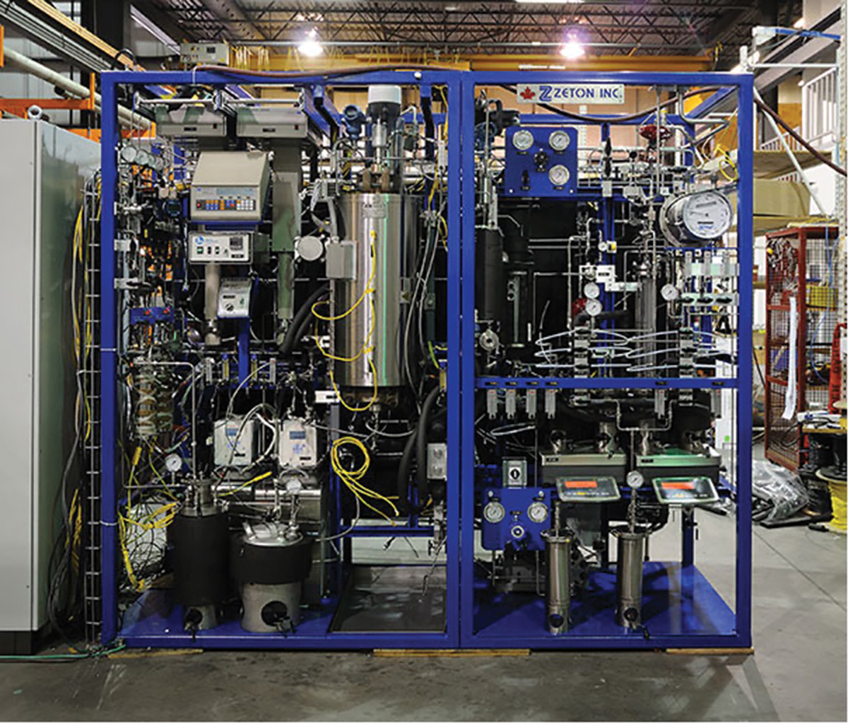
▲Figure 1. Unlike in commercial plants, meeting layout constraints in lab-scale systems and pilot plants is particularly challenging.
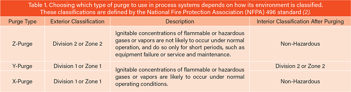
Flammable and toxic materials. A strategy often deployed in smaller units where a key piece of process equipment does not have adequate hazardous area approvals is to install the devices within an enclosure and use purging and pressurization, per the National Fire Protection Association (NFPA) 496 standard (2). This code specifies three classifications of purging and pressurization, and each one permits a reduction of the hazardous area division or zone within the enclosure (Table 1).
Due to the prevalence of Div. 2 or Zone 2 installations, this section primarily focuses on Z-purging. Z-purging reduces the classification within a protected enclosure from Div. 2 or Zone 2 to nonhazardous. At a minimum, Z-purges require four key components:
- enclosures that can maintain a slight positive pressure, such as a National Electrical Manufacturer Association (NEMA)-rated electrical cabinet
- the supply of a protective gas (instrument air or nitrogen are common)
- an audible alarm in case the enclosure fails to maintain the specified pressurization levels (a minimum 0.1 inH2O is required)
- a way to purge the enclosure prior to pressurization.
Although the code allows the engineer to develop a design that meets its requirements, it is common to see products installed that are specifically designed to facilitate or even automatically carry out the appropriate purge and pressurization steps (Figure 2). These will typically come with the ability to switch between a large purge flowrate and a smaller pressurization flowrate of the protective gas. Additionally, they often include a relief valve specially designed to minimize backpressure during the purge step and crack open at pressures below 1 inH2O when the enclosure is pressurized.
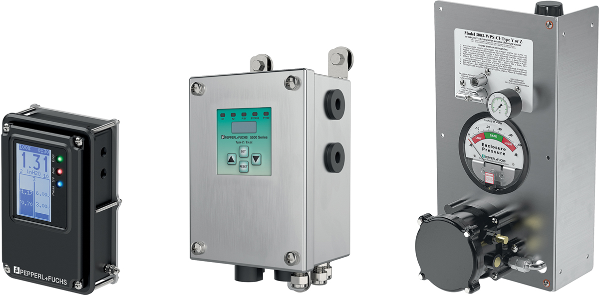
▲Figure 2. The complexity and sophistication of Z-purge systems vary and are chosen based on the safety requirements of the small-scale system.
Whenever a Z-purged enclosure is opened or loses pressurization, it is possible for hazardous gases to invade the enclosure. Since these gases eliminate the protections provided by Z-purging, a purge step is performed to expel them. To do so, a high flowrate of protective gas is introduced into the enclosure. The purge is maintained until a specified amount of inert gas — equivalent to a minimum of four enclosure volumes — has flowed into and vented out of the enclosure. During this process, an internal pressure of at least 0.1 inH2O must be maintained. Following the completion of the purge step, it’s assumed that operation is safe to resume. While the plant is operating, the Z-purged enclosure must maintain the minimum pressurization. As most enclosures are not leak-tight, this typically involves constantly flowing a small amount of protective gas through the space.
When dealing with materials that are both flammable and toxic, the traditional approach of purging and pressurization to prevent ignition may not suffice. Purging with an inert gas like nitrogen and then pressurizing an enclosed space does reduce the risk of combustion, but it also introduces new safety hazards. Without constant purging, a leak from the process equipment within the enclosure can lead to a buildup of toxic gases and, ultimately, an exposure incident when the enclosure is opened by personnel. As such, purging and pressurization is only recommended if there are no fittings inside the enclosure that could leak. Alternatively, it is acceptable if a properly implemented post-purge procedure is established. A post-purge procedure could be as simple as ensuring the Z-purge unit’s automated purge step is carried out after shutdown and before opening the enclosure, or it could be more complex. It’s important that the purge vent is routed to a safe location, such as a flare or scrubber, and that toxic gas detection methods are in place. Ultimately, the plant owner is responsible for developing and implementing the specifics of any safety protocols.
Fired or hot equipment. When a process must operate at very high temperatures, it is common to see fired equipment or high-temperature electric heaters being used to meet this requirement. While excessive heat can be the cause of several process upset conditions, it also presents an obvious safety concern: hot surfaces. In general, insulation, barriers, or guards can be used to keep personnel from burning themselves, thus mitigating the hazard. However, it becomes especially important to consider this hazard when plant surface temperatures exceed the auto-ignition temperature (AIT) of the process gases. In this case, relying only on electrical area classification to prevent ignition is insufficient because the electrical devices are not the only source of ignition available to complete the fire triangle. Therefore, other measures must also be considered, such as:
- Zone(s) of exclusion. In some cases, hot or fired equipment can be isolated from the rest of the plant. While this can often be difficult given the aforementioned space constraints typical of small-scale plants, it can still be achieved with careful planning.
- Ventilation and gas detection. A benefit of the small footprint of these units is that they can often fit within a standard fume hood. If these hoods are equipped with appropriate gas detection instruments, this combination can effectively mitigate flammability and toxicity risks. Ventilation prevents the accumulation of hazardous vapor or gas concentrations, while detection systems alert personnel to any buildup in the event of inadequate ventilation.
Regardless of the approach taken, there are a few points to always keep in mind:
- In the case of electric heaters built per the National Electric Code (NEC), a temperature code (T-code) is sometimes provided, which indicates the maximum temperature an external surface of an electrical device will reach. However, its application can be inconsistent. Although all external surfaces of the electric heater should be considered when determining a T-code, some manufacturers provide a T-code for the heater junction box, while others provide separate T-codes for the junction box and process connection. Regardless, the T-code is only intended to apply to exterior surfaces of the device, so it does not apply to the heating elements, heater shell, or junction box internals, nor does the rating render the equipment safe for use in a hazardous area without other mitigating measures.
- Insulation is not gas-tight. While insulation is effective at reducing the risk of burns to personnel, flammable materials can make their way to the hot surfaces beneath the insulation and ignite.
- Purging and pressurization is an impractical strategy for containing hot process equipment and may introduce secondary hazards. Any enclosure needs to be designed to handle the elevated temperatures of the process, effectively turning it into an oven. If there are components on the equipment that cannot handle these high temperatures, such as on-board controllers or other electronics, then the enclosure must have a cooling system. Enclosures also reduce the available space around hot equipment for operators to maneuver, thereby increasing the risk of burns from hot surfaces.
Designing relief systems for small plants
A relief system encompasses all equipment, devices, and piping required to safely vent process fluids to the atmosphere and is used to prevent process equipment from exceeding its maximum allowable working pressure (MAWP). Equipment such as scrubbers or flares are often additionally employed to ensure hazardous and toxic chemicals are appropriately handled prior to venting.
Relief devices, such as relief valves or rupture discs, are critical elements in the safe design and operation of process facilities of all scales. For all systems, it is best practice to follow the rules of relief sizing set by the American Petroleum Institute (API) 520 and API 521 standards (3, 4). However, the implications of choices made within the framework of these rules can be more impactful for small-scale plants. Because the overall size of a relief system is directly impacted by the amount of fluid discharged by its various relief devices (either separately or coincidentally), oversizing relief devices indirectly affects the sizing of the entire relief system, potentially leading to wasted money and space. As such, a pragmatic approach to determining the credibility of certain relief cases per API 521 is necessary, and the size and type of relief device selected need to be considered in ways that are appropriate for a smaller system.
Relief device size and type. The American Society of Mechanical Engineers (ASME) uses so-called U-stamps to certify a manufacturer has met quality-control requirements set by ASME boiler and vessel code. As a general rule, an ASME pressure vessel carrying a U-stamp must be protected by a relief device that also carries an ASME certification. At process scales large enough to require piping for the main process lines, such a pressure vessel will commonly be protected by an ASME relief valve per code requirements. In these situations, the inlet and outlet piping for the ASME relief valve are proportional to the rest of the system’s piping, and routing is no more complicated than the pre-existing piping.
However, on a system operating at a scale where fractional tubing is large enough to handle process flowrates, the smallest available ASME relief valve may provide a rated relief flow that is orders of magnitude greater than the minimum required relief rate. This rated flow becomes the sizing basis for the inlet and outlet piping, the relief header, and any downstream relief equipment, such as a knockout (KO) vessel or scrubber system. This causes these pieces of equipment to be drastically larger than necessary. Given the usual space constraints of smaller systems, accommodating this larger relief system could significantly complicate the layout, operation, and maintenance of the plant, as well as unnecessarily increase the cost of the unit.
A potential alternative is to consider a rupture disc instead of a relief valve. Although a relief valve has benefits that a rupture disc lacks, such as re-seating, rupture discs have different sizing rules associated with them that can help keep the relief system at a size more proportional to the overall unit.
Pool fire scenarios. Of the various overpressure scenarios listed in API 521 (4), external fire, or pool fire, is often the most significant scenario when sizing the relief system. A pool fire scenario exists when a large quantity of liquid fuel collects and ignites. When designing for this scenario, engineers must consider a large and sustained heat flux into the walls of the pressure equipment, which would boil off any liquids contained within and relieve them as vapor. Assuming that pool fires will often encompass multiple pieces of equipment, the engineer may need to consider coincident relief of all devices in the zone, making the magnitude of this relieving event even more pronounced. In a small system, the extent of a pool fire could be the entire plant (Figure 3), which would require considering the coincident relief of every relief device installed.
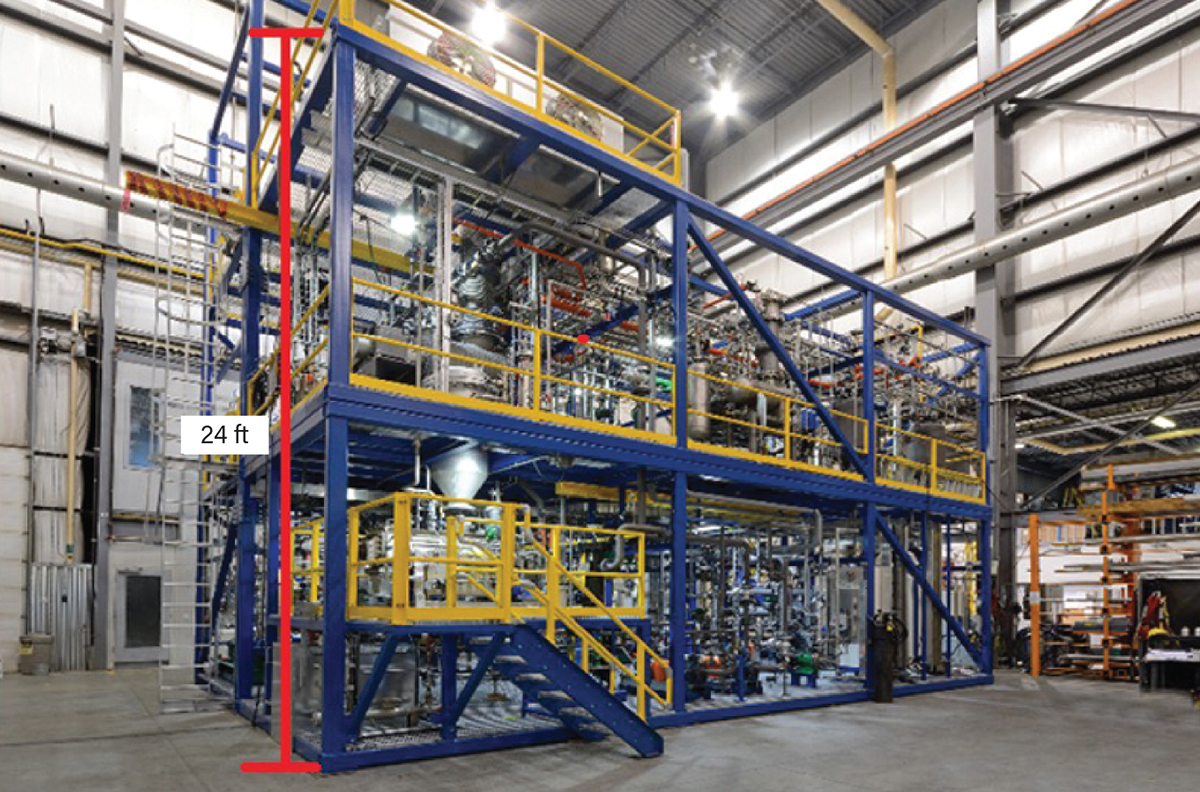
▲Figure 3. A pool fire scenario, in which a large quantity of liquid fuel collects and ignites, can span more than 2,500 ft2 (30-ft radius) and reach more than 24 ft in height.
Unnecessarily designing for a pool fire scenario where a sustained pool fire is not feasible can lead to drastically oversizing and overcomplicating a small plant’s relief system. If the unit is to be sited in an existing facility, oversizing can even preclude using existing relief equipment such as flares or scrubbers. A more practical approach may involve assessing the true volume of flammable liquids present and considering whether they could sustain a pool fire, therefore avoiding the need for oversized relief systems.
Before designing for a pool fire, it is beneficial to evaluate the total volume of flammable liquids within and near the plant. This involves taking a detailed inventory of all flammable substances and their storage conditions. If the volume is insufficient to sustain a pool fire, designing relief systems for a pool fire scenario may be unnecessary. This assessment can lead to more appropriately sized and cost-effective safety systems.
If the evaluation shows that there is sufficient liquid present that can plausibly spill and sustain a pool fire, developing systems to manage the total inventory present at any one time is a further step that can be taken to discredit the pool fire scenario. A straightforward example of this is investigating whether flammable liquids that are being stored near the unit could be stored elsewhere.
Ensuring robust management of change systems
Lab-scale systems and pilot plants often serve as testing grounds for proof-of-concept, process enhancement, product innovation, or scale-up of new technologies. Due to their experimental nature, these systems frequently undergo changes during design and after fabrication. The dynamic nature of lab-scale systems and pilot plants means that changes in process parameters, equipment, and configurations are common, especially those needed to accommodate new discoveries made during the pilot campaign. Each change, no matter how minor, can introduce new risks or alter existing ones. An effective and robust management of change (MOC) system ensures that all changes are documented, reviewed, and approved by competent personnel, maintaining the integrity of the safety protocols.
Running multiple processes in a single unit. A great advantage of small systems is how easily a design can be adapted to run multiple different processes. Tubing lines can easily be modified and re-routed, ample instrumentation and valving are often included, and oversizing equipment for the largest possible process demand is relatively inexpensive compared to larger scales.
With any new process comes new potential hazards that may not have been considered in a prior safety review. For instance, new materials could be pyrophoric or more corrosive, solids may precipitate and cause plugging, electric heaters may cause thermal degradation due to hot spots, or sparging gases may be reactive. While a hazard and operability (HAZOP) study can be performed on the unit to the fullest extent possible, each new process must be specifically considered through the HAZOP lens prior to startup so that prior safety provisions are not taken for granted erroneously.
Independent reviews. As is often the case when people develop proficiency in something, aspects of their work and thinking can become reflexive. Repeatedly performing the same task can be advantageous and efficient, but when critical thinking and analysis are suddenly required due to some change, mental shortcutting can lead to serious oversights.
This is especially true in the safe design and operation of a lab system or pilot plant that has been operating successfully for some time; reflexive thinking and relying on assumptions when reviewing proposed design changes can have serious safety implications. For this reason, it is beneficial to bring in someone who is not familiar with the unit to assist with reviewing any proposed changes. This could be anyone qualified in the material, including a coworker with no prior experience on the unit or a HAZOP facilitator.
Procedures and training. There are very few cases where a process unit can run fully autonomously on a continuous basis without the intervention of human operators. The thoughtful development of operating procedures specific to each process being run is crucial to personnel safety. Equally important is ensuring these procedures are routinely updated and adapted with each process change and that personnel are thoroughly trained.
Testing candidate materials of construction
Material compatibility is a major unknown in many novel processes, and a process without a viable material of construction at the commercial scale is not worth scaling up. While choosing an inadequate material of construction can lead to a variety of hazards associated with rapid corrosion and loss of containment, unnecessarily using higher-quality materials at production scales can be prohibitively expensive. Therefore, it is critical to both the safety of a process and its commercial viability to use the most cost-effective material that provides appropriate longevity to the wetted parts.
Laboratories often use glass equipment when experimenting with new chemistries. Glass is an excellent material for early-stage work because it has tremendous chemical compatibility and is lightweight; this combination is ideal for reconfiguring test apparatuses to handle multiple chemistries cost-effectively. Conversely, glass has numerous disadvantages that prevent it from being used at larger scales. Its chief shortcomings are its fragility and inability to handle pressure at large scales. Because glass is not a viable commercial-scale material, studies that investigate the effects of process chemicals on various materials must be undertaken. Even after obtaining this information, there may still be uncertainty about the materials’ viability, given that true plant operating conditions were not simulated.
At smaller scales, fabricating plant components from more exotic construction materials costs less on an absolute basis than fabricating the same items at larger scales. As a result, it can be beneficial to increase the small-scale system budget to accommodate a higher alloy for the unit, then use corrosion coupons during operation to test the viability of lower candidate materials under actual operating conditions. While this may seem like overkill, it can be relatively inexpensive insurance against loss of containment due to corrosion in the lab or pilot unit, with the added benefit of learning which materials are compatible with the process. When the process is scaled up, owners can then choose the most appropriate material of construction for their process without being too conservative and opting for more expensive materials.
As a practical example, consider a process where stainless steel is an appropriate material of construction in the feed and product handling sections of a process. In the unit’s reactor, however, increased temperatures and pressures may cause suspended solids to erode the walls during prolonged operation, and side reactions are possible if contaminants are present. Although the corrosion studies suggested stainless steel would be a suitable material, the engineer might hesitate to select it given the potentially incomplete set of inputs in the prior corrosion tests and the unpredictable nature of operating a pilot plant. Instead, Hastelloy C276 (a nickel-chromium-molybdenum alloy) might be chosen for the reactor material since it showed excellent performance in prior corrosion studies.
Closing thoughts
At production scales, companies spend significant time and effort developing corporate standards and specifications that take the guesswork out of the design and operation of their process units. These standards are an invaluable resource and have assuredly saved many lives because of the hazards they have prevented.
While these standards are crucial at larger scales, applying them at smaller scales without careful consideration is often impractical due to the limited physical space, tighter budgets, and sometimes sparse availability of smaller versions of specified parts. Instead, a more flexible way of thinking is required with safety, scale, and creativity in mind. This is essential through each phase of a small system’s lifespan, beginning during design and carrying through each change made to the unit until its ultimate decommissioning.
* This article is based on a presentation given at the 2023 AIChE Annual Meeting (Orlando, FL, Nov. 5–10, 2023).
Literature Cited
- Bhishikar, P., “Overlooked Considerations During Safety Reviews of Lab Scale Systems and Pilot Plants,” presented at the 2023 AIChE Annual Meeting, Orlando, FL (Nov. 7, 2023).
- National Fire Protection Association, “Standard for Purged and Pressurized Enclosures for Electrical Equipment,” NFPA 496, NFPA, Quincy, MA (2024).
- American Petroleum Institute, “Sizing, Selection, and Installation of Pressure-Relieving Devices, Part II — Installation,” Standard 520, 6th Edition, API, Washington, DC (Mar. 2015).
- American Petroleum Institute, “Pressure-Relieving and Depressuring Systems,” Standard 521, 7th Edition, API, Washington, DC (June 2020).

Copyright Permissions
Would you like to reuse content from CEP Magazine? It’s easy to request permission to reuse content. Simply click here to connect instantly to licensing services, where you can choose from a list of options regarding how you would like to reuse the desired content and complete the transaction.