
Sections
Condition-based monitoring technologies can support both equipment reliability and process safety goals.
Maintenance practices — including preventive maintenance (PM), inspection, testing, autonomous maintenance, and predictive maintenance (PdM) — are components of an equipment reliability program and are part of the Occupational Safety and Health Administration’s (OSHA’s) process safety management (PSM) regulation. However, companies often work in silos where process safety departments and maintenance groups may not effectively share and leverage information that can improve equipment reliability and inherently improve process safety performance.
This article defines and describes the differences between key maintenance terms — such as PM, PdM, and condition-based monitoring (CBM) — and provides an overview of maintenance and reliability basics for process safety engineers who are less familiar with those practices. The article also provides examples of CBM technologies, explains where CBM is applied, describes the relationship between PdM practices and process safety goals, and highlights the need to prioritize applications as available technology solutions continue to expand.
Introduction
Maintenance practices, including PM, inspection, testing, autonomous maintenance, and PdM, are components of equipment reliability programs. Maintenance, inspection, and testing requirements are referenced generically in the OSHA PSM regulation. Despite this linkage, process safety engineers may be unaware of the range of maintenance practices that are available to support the health of process equipment.
By design, qualitative studies, such as hazard and operability (HAZOP) studies, and semi-quantitative studies, such as a layers of protection analysis (LOPA), lack the granularity to fully describe all hazard scenarios. Some failure causes and certain safeguards do not fit neatly into the process hazard analysis (PHA) model. Maintenance practices are sometimes listed generically as safeguards in PHAs but cannot be credited in LOPA studies as independent protection layers (IPLs). For this reason, some PHA teams prefer not to mention maintenance plans or procedures in the PHA study.
However, having more knowledge and awareness of available maintenance practices and technologies can be beneficial to PHA teams, particularly when addressing higher hazard scenarios that have few available safeguards. The application of predictive maintenance technologies can positively impact hazard scenarios and help to reduce process safety risk.
Terminology and definitions
The internet is loaded with reference materials that provide both general and specific information on maintenance practices, as well as definitions of the terminology. However, there is some variability in the usage of certain terms, such as CBM and PdM. This section provides brief definitions to ensure a basic understanding of the practices and to communicate how the terms will be used in this article.
- Preventive maintenance (PM) refers to plans and procedures to perform parts replacements, inspections, and testing on equipment and components on pre-defined scheduled intervals. The intervals may be calendar-based or runtime-based. PM typically requires the equipment to be offline and is usually invasive (i.e., equipment is partially disassembled). PM is generally performed by technicians with specialized skills associated with the task and equipment.
- Autonomous maintenance (AM) refers to the monitoring of equipment parameters on a routine basis by operators. The monitoring and inspection may include: checking process parameters such as pressures, temperatures, level, flow, etc.; checking equipment parameters such as vibration, oil levels, parts temperatures and pressures, etc.; and inspecting the equipment for leaks, unusual noise, movement, etc.
- Condition-based monitoring (CBM) typically refers to a suite of technologies used to take measurements and make interpretations about equipment health. The data is taken from the equipment itself rather than from the process media. These data can indicate symptoms that an early-stage failure is progressing. The data is gathered on scheduled intervals or continuously. Data gathering involves the use of sensors, handheld devices, sampling, and/or analysis software, and the data is interpreted by skilled technicians. An extended definition of CBM may include routine monitoring of certain parameters by unit operators at the equipment or board operators through automation. In all cases, whether monitored by technicians on scheduled intervals or continuously by automation, the data gathered allows for the assessment of equipment health.
- Predictive maintenance (PdM). Some practitioners use the terms CBM and PdM interchangeably (1, 2). Some believe that PdM means processing multiple CBM parameters and additional data using analytics tools, machine learning (ML), and/or artificial intelligence (AI) for the purpose of predicting incipient failure progression sooner in the process of degradation (2–4). This article uses the terms interchangeably. Our rationale is that although it is theoretically possible to predict failure progression somewhat earlier using advanced analytics, from a practical standpoint in many industrial applications, the incremental value of earlier prediction and response may be negligible. As shown on generalized curves depicting equipment deterioration vs. cost to repair (Figure 1), the cost to repair changes little in the early stages of decline. Figure 1 highlights the regions of the curve in which CBM technologies provide early indications of equipment degradation.
- Corrective maintenance refers to work done to repair equipment and to return it to its original condition or within its specification tolerances. Repairs may involve replacing or refurbishing worn or damaged parts like-for-like. Repairs do not include any modifications or upgrades of equipment or parts. Corrective maintenance may be associated with failures, reactive work, or findings from PM or PdM work.
- Reactive maintenance refers to work done to repair and restore equipment in response to failures, breakdowns, and unplanned events.
- Proactive maintenance refers to planned and scheduled work intended to maintain equipment health and prevent failures. Proactive maintenance includes PM, inspection, testing, AM, CBM, and PdM.

▲Figure 1. Over time, equipment health degrades and equipment repair costs increase. Predictive maintenance (PdM) using condition-based monitoring (CBM) can help detect impending failures in earlier stages.
Figure 2 shows the relationship between all of the maintenance practices discussed in this section. Practices become increasingly more proactive when moving to the right on the diagram.
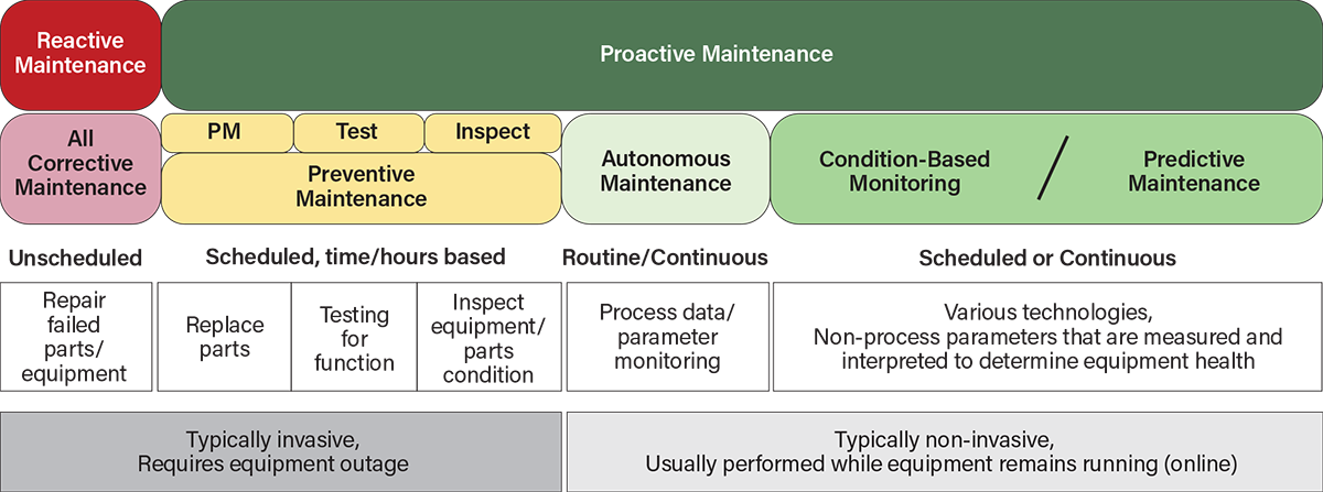
▲Figure 2. This graphic shows an overview of how maintenance practices relate to each other. Practices become increasingly more proactive when moving to the right. When working in the reactive mode, work is unscheduled. Moving from preventive maintenance (PM) to PdM allows for less-invasive inspection of the equipment condition.
CBM technologies
Numerous CBM technologies are available to measure the health of process equipment (5–8). These technologies include vibration monitoring, thermography, oil analysis, pressure analysis, motor circuit analysis, electrical monitoring, electromagnetic measurement, ultrasonic testing (UT), including airborne ultrasonics (AU) and acoustic emissions (AE), among others.
Data gathered using these technologies allow early-stage equipment failures to be detected. Certain datasets, such as vibration data, allow for diagnostic interpretation that can identify the specific failure mechanism that is occurring in the rotating equipment, such as misalignment, unbalance, or bearing failure, among others (9). Extensive reference material is available online and in books describing these technologies and their applications. Of those listed, vibration monitoring, thermography, ultrasonics, oil analysis, motor circuit analysis, and pressure monitoring/analysis tend to be the most commonly used (5).
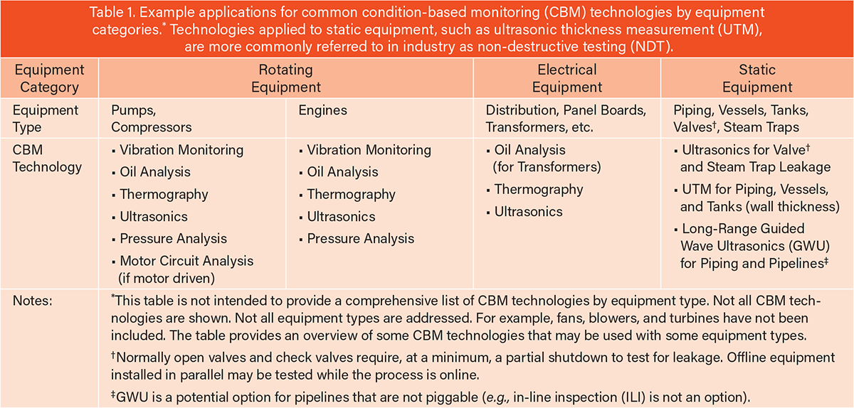
CBM is heavily focused on maintaining the health of rotating equipment, but certain technologies can also be applied to electrical equipment. Inspection methods for static equipment, including piping, vessels, and tanks, tend to be referred to as non-destructive testing (NDT) rather than CBM. However, standard NDT methods, such as ultrasonic thickness measurement (UTM), are a type of condition-based monitoring. UTM is used to interpret wall thickness and equipment condition. Newer technology, such as guided wave ultrasonics (GWU), has enhanced capabilities for detecting wall thickness anomalies over longer sections of piping (10). Like other CBM technologies, these tools are non-invasive and can be applied while the process is in service. In-line inspection (ILI) of piggable pipelines is another form of NDT, but it is a highly specialized and high-cost service that requires separate discussion.
Ultrasonics, including AE, can be used to detect leakage across steam traps, check valves, and block valves. However, an equipment outage would be required to detect check valve leakage or leakage through normally open block valves when closed. Table 1 provides an overview of common CBM technologies that may be applied to various categories of equipment.
Hazard scenarios: Where can CBM help?
How does CBM play into process hazard analysis and process safety risk mitigation in general? Looking at the familiar bow-tie diagram in Figure 3, we see the parts of the hazard scenarios that CBM touches. The primary impacts of an effective CBM program will be on the cause, or initiating event frequencies, for certain scenarios. Rotating equipment failure frequencies that result in the equipment tripping offline can be reduced using CBM. Reducing these unplanned equipment trips has several safety benefits, which include:
- reduction in cause frequency, i.e., initiating event likelihood (IEL), for scenarios involving rotating equipment tripping offline and the associated potential reverse-flow scenarios. The study is directly impacted if actual rather than generic IEL values are used.
- fewer unscheduled major repairs and associated energy isolations. These unscheduled activities have inherent safety risks. So, reducing the number of equipment trips reduces the risks associated with those activities.
- fewer restarts associated with unscheduled repairs, meaning fewer associated start-up/shutdown hazards.
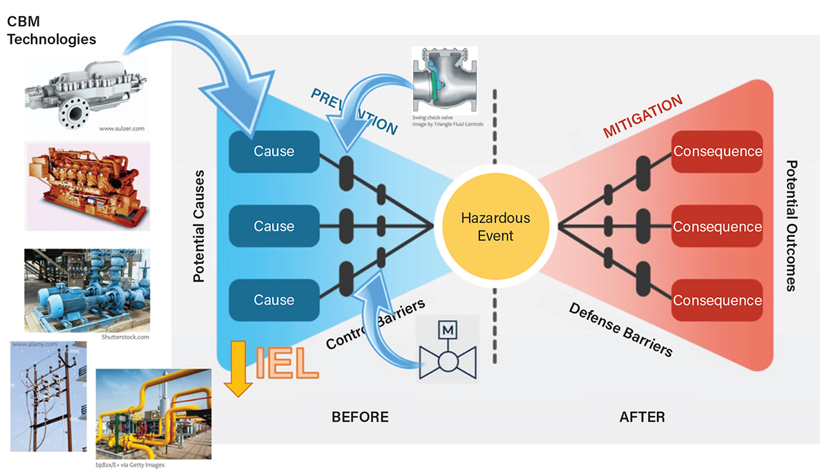
▲Figure 3. Hazard scenarios can be impacted by condition-based monitoring (CBM). For instance, applying CBM technologies can support lowering the initiating event likelihood (IEL) of potential causes or can confirm the performance of certain preventive safeguards.
CBM technologies can detect progressing failures in earlier stages in order to prevent mechanical seal leaks in rotating equipment. Preventing seal leaks is important because seal failures tend to be one of the most common failure modes in rotating equipment (11, 12). They can also result in loss-of-containment (LOC) events as process media may be leaked into the environment, potentially resulting in a process safety incident.
Hazard scenarios involving widespread or isolated electrical outages are improved in a similar manner by reducing the frequency of the outages that initiate the scenario. Likewise, static equipment failure frequencies are reduced by monitoring for corrosion via wall loss. (Note: wall loss due to erosion typically occurs too quickly to be manageable through a UT inspection program.) Despite those impacts, HAZOP and LOPA methods are recognized as not being ideal tools for assessing certain scenarios such as corrosion. However, as corrosion-related failures are a common cause of incidents, the HAZOP/LOPA study would be incomplete if the potential for corrosion-related failures is not addressed, and the impacts are not understood and mitigated.
Using ultrasonic technology to inspect for check valve and/or block valve leakage and then addressing problems found can lower the probability of failure on demand (PFD) for these safeguards in hazard scenarios. Check valves, including critical check valves, have historically received inadequate maintenance attention (13, 14). And isolation valves involved in safety instrumented functions (SIFs) or non-SIF interlocks are rarely inspected for leakage. Using this CBM technology can support understanding the health of these safeguards and improve their reliability.
Rotating equipment seal failure scenarios
Because mechanical seal failures involve the potential for loss of containment, the remainder of the article discusses seal failure examples and how this failure mode is commonly addressed or may be mischaracterized in HAZOP/LOPA.
Mechanical seal failure frequency and causes. When pump failures are broken down by component, seal failures are often found to be the part that has the highest failure frequency (11, 12). Those seal failures have numerous causal factors and initiating events that begin the progression toward that ultimate seal failure. Initiating events (also known as incipient failures) include (15, 16):
- inadequate seal flush flow or contaminated seal flush
- seal liquid vaporizing at the seal surface (i.e., seal face flashing)
- high pressure on the seal faces
- overloaded seal faces
- incorrect materials used
- improper clearances
- a vibration issue caused by: shaft or coupling misalignment; bent shaft; piping strain; eccentricity; worn pump; among others
- operating parameters out of specified range
- many other causes.
Each of those initiating events and the subsequent failure progression represents a rung on a root cause analysis that can be depicted in various ways.
PHA teams typically identify several scenarios that may lead to a potential seal failure event. Those scenarios usually include blocked suction (no flow, low suction pressure), blocked discharge (no flow, high discharge pressure), or pump run out (low discharge pressure, high flow). Whether those scenarios always lead to seal failures can depend on the type of equipment involved, the seal flush design, the duration of the deviation, and other conditions. But a conservative assumption is to assume that there could be a seal failure. In the case of potential seal failures precipitated by these process deviations, alarms with operator action, shutdowns, and/or recycle loops can potentially serve as preventive safeguards and/or IPLs (Figure 4).
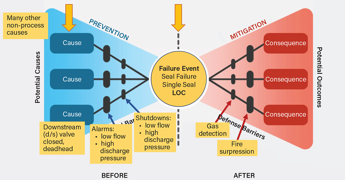
▲Figure 4. A hazard scenario involving an operational process deviation can lead to a seal failure and loss of containment (LOC). These types of scenarios are commonly covered in hazard and operability (HAZOP) studies and layers of protection analyses (LOPA), but scenarios stemming from process deviations only represent a small fraction of potential causes for seal failures.
However, as demonstrated with the aformentioned list, there are many other causes of seal failures in rotating equipment. It would not be practical to independently define each initiating event in a HAZOP/LOPA study for this type of failure event. Many potential initiating events and most event progressions would not be detectable using parameters that PHA teams usually associate with preventive safeguards and IPLs. However, CBM technologies can be used to detect some of those failure modes and help prevent the eventual seal failures.
In the Center for Chemical Process Safety (CCPS) book, “Guidelines for Initiating Events and Independent Protection Layers in Layer of Protection Analysis,” pump primary seal leak is listed generically as an initiating event with a once-per-year likelihood for minor leaks. Complete failure of the primary seal is listed with an initiating event frequency (IEF) of 0.1/yr (17). As noted in Figure 4, seal failure is the failure event, not the initiating cause. However, multiple non-process-related initiating events could be aggregated together in the HAZOP to represent seal failures due to other causes. Aggregating those incipient causes for seal failures and considering the consequences and needed safeguards (such as CBM) is prudent in the PHA study. Where no preventive safeguards are present or can be added, the PHA team needs to ensure that reliable mitigative safeguards are present.
Case study of customized CBM application used to address seal failures. In an oil field location, the CBM team had begun using a suite of CBM technologies to support their equipment reliability improvement efforts. Those technologies included vibration analysis, ultrasonics, oil analysis, thermography, and motor circuit analysis. Those technologies were being selectively applied to critical equipment as the program developed. Around this time, a series of repeat seal failures began occurring on high-pressure multi-stage waterflood injection pumps. On one occasion, the mechanical seal failed suddenly and parts blew out.
In conjunction with root cause analysis, it was found that the throttle (i.e., throat) bushing was worn and out of specification. This wear may have been caused by abrasive filter media passing through the filters into the process stream. Other potential causes were investigated, as well. The worn throttle bushing allowed a higher flow of seal flush fluid into the seal stuffing box, but flow was restricted by design at the outlet. This situation resulted in high pressure within the seal stuffing box. Figure 5 overlays this specific failure progression on the generic pump health vs. repair cost set of curves.

▲Figure 5. In the case study, a pump seal failure resulted from throttle bushing wear that stemmed from abrasive material being present in the process media. The failure progression is superimposed on generalized curves showing pump health and repair cost over time.
Upon understanding this failure mechanism, the CBM team created a customized CBM program to prevent the recurrence of these seal failures. The custom CBM program included adding a new differential pressure (dP) reading that would compare the seal stuffing box pressure to the pump suction pressure. This dP reading was brought into the plant supervisory control and data acquisition (SCADA) system and alarms were set for high differential pressure. Operators were trained on routinely monitoring the dP and on how to respond to the alarm. Along with the dP transmitter that was added, additional CBM technologies were applied to the pumps, including using ultrasonics to detect discharge check valve leakage on the offline pump while the other pump was in operation.
This suite of technologies evolved into a customized pump health analysis program (similar to the compressor and engine analyses programs that were being used for those equipment types). The pump health analysis CBM program proved successful as failure rates and costs were reduced while runtimes were improved. Figure 6 overlays this specific failure example and CBM program description onto the curves previously shown.
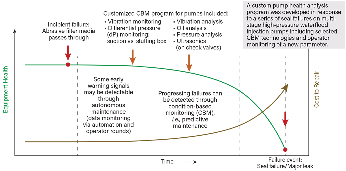
▲Figure 6. To address the throttle bushing wear failure mode as well as other potential failure modes, the facility implemented a customized suite of CBM technologies. These CBM methods allow for the assessment of pump health and support the prevention of major failure events.
Using CBM to prevent primary seal failures, not just LOC
The previous section discussed the failure of single mechanical seals in rotating equipment. When the single seal fails, an LOC event occurs. When processing highly hazardous fluids, dual seals or tandem seals provide another layer of protection against an LOC event. The secondary seals and their associated seal fluid outlet piping provide secondary containment for the leaked process fluid. Note that the disposal of this leaked process fluid presents a secondary hazard if the fluid is not routed to a safe location, preferably to enclosed process equipment. If the fluid is relieved to the atmosphere, that location should be evaluated for its acceptability. The leaked fluid should not empty into a poorly ventilated or confined space.
Seal plan configurations are defined in guidance standards, such as the American Petroleum Institute’s API 682. The arrangements are described in detail in various references (18, 19). Because of the additional protection against loss of containment provided by the enclosed seal plan arrangements, some PHA teams view the safeguards associated with the seal plan system as preventive safeguards. These safeguards do support the prevention of an LOC event, but they do not prevent the primary failure. Unlike other preventive safeguards like relief devices that act before equipment damage occurs, in this case, the safeguards activate after the damage is done. So, they are not preventive for protecting against equipment damage (Figure 7).
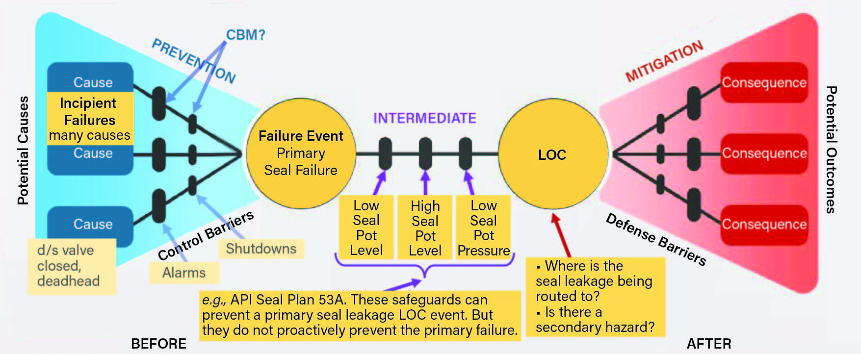
▲Figure 7. For pumps with a dual or tandem pump seal, safeguards associated with the seal plan system prevent the LOC event but not the primary seal failure. CBM may be the only available option to detect the progression of some failures.
As with single seal failures, primary seal failures precipitated by out-of-range process parameters represent a small fraction of the initiating causes. Some seal failure modes may only be preventable by applying CBM technologies to detect and respond to the symptoms before the primary seal failure event occurs.
CBM program development and prioritization
CBM programs are implemented by equipment reliability/maintenance groups within the company. Therefore, the CBM program development would naturally be driven by the priorities set by that team, which likely include addressing critical equipment such as large equipment with high costs to repair in the event of catastrophic failures, essential non-spared equipment, and equipment that experiences repeat failures.
Improvements in equipment reliability will inherently improve safety. However, focused attention on process safety drivers may lead to additional candidate equipment being added to the program. Process safety drivers can be derived from PHAs and root cause failure investigations. These drivers could include:
- Equipment involved in high-consequence scenarios. Could a leak or failure result in a fatality or significant health hazard?
- Equipment involved in scenarios that are protected by only mitigative safeguards
- In the case of dual or tandem seals, scenarios lacking preventive safeguards. Are the safeguards present intermediate safeguards? Are any safeguards present to prevent the primary seal failure? Additionally, consider any secondary consequences associated with routing leaked process fluid from a failed primary seal.
- Situations where applying CBM could lower the initiating event likelihood of a high-consequence scenario or address a scenario where risk targets are not met.
The design and application of the CBM tools is beyond the scope of process safety personnel or the PHA team. However, understanding potential opportunities to reduce risk in higher hazard scenarios — along with using a collaborative approach to set maintenance priorities — can link the efforts of the process safety group more directly with the reliability group. The applications need to be effectively prioritized to focus the improvement efforts on the most critical needs.
Closing thoughts
While technology solutions continue to expand, scarce resources require that CBM technologies be applied selectively to equipment where risk is the greatest. Risk may be commercial, reputation-related, environmental, and/or safety-related. Maintenance practices can be optimized by ensuring that safety-critical equipment definitions correlate with process hazard analyses and other risk assessments. Incidents can be avoided by applying proactive maintenance, inspection, and testing practices to critical equipment and safeguards.
Acknowledgments
The authors wish to thank Brooke Beveridge, Swarup Bade, and Mark Bergstrand for their review, comment, and contributions to this article.
Literature Cited
- Society for Maintenance & Reliability Professionals (SMRP), “SMRP Best Practices 5th Edition, Maintenance & Reliability Body of Knowledge,” SMRP, Atlanta, GA (2017).
- Gabani, A., “Is Condition Based Maintenance (CbM) the Same as Predictive Maintenance (PdM)?” LinkedIn, www.linkedin.com/pulse/condition-based-maintenance-cbm-same-predictive-pdm-ashvin-m-gabani (May 8, 2021).
- ReliaSol, “Why is Condition Monitoring Not Always Enough and Why is Predictive Maintenance Worth Implementing?” ReliaSol, www.reliasol.ai/condition-monitoring-vs-predictive-maintenance (accessed Jan. 2023).
- Hanly, S., “Differences Between Condition-Based, Predictive, and Prescriptive Maintenance,” Endac, blog.endaq.com/differences-between-condition-based-predictive-and-prescriptive-maintenance (accessed Jan. 2023).
- Weilbaker, T., “Condition Monitoring Technologies – Pros and Cons of the Top Five,” CBM Connect, www.cbmconnect.com/condition-monitoring-technologies-pros-and-cons-of-the-top-five (July 12, 2021).
- ETS Solutions, “Condition Monitoring Techniques, Applications, and Tools,” ETS Solutions, www.etssolution-asia.com/blog/condition-monitoring-techniques-applications-and-tools (June 11, 2021).
- UpKeep “Condition-Based Maintenance (CBM) Explained,” Upkeep, www.upkeep.com/learning/condition-based-maintenance (accessed Jan. 2023)
- Infraspeak, “9 Condition Monitoring Techniques You Must Know,” Infraspeak, blog.infraspeak.com/condition-monitoring-techniques (Feb. 14, 2023).
- Buscarello, R. T., “Practical Solutions to Machinery and Maintenance Vibration Problems,” Update International, Inc., Denver, CO (Oct. 1992).
- Rose, J. L., et al., “Ultrasonic Guided Wave NDE for Piping,” Materials Evaluation, 54 (11) (Nov. 1996).
- Grundfos, “Grundfos. Mechanical Shaft Seals for Pumps, Chapter 5: Failure of Mechanical Shaft Seals,” Grundfos Management A/S, api.grundfos.com/literature/Grundfosliterature-5768950.pdf (2009).
- Sutton, I., “Plant Design and Operations, Chapter 12 — Equipment,” pp. 264–286, Gulf Professional Publishing, Houston, TX (2015).
- Patschke, C., “Solving the Mysteries of Critical Check Valves,” Inspectioneering, inspectioneering.com/journal/2018-06-28/7745/solving-the-mysteries-of-critical-check-valves (May/June 2018).
- Olsen, J. E., “Crediting Check Valves as IPLs? Testing Protocol to Better Understand Check Valve Reliability,” Process Safety Progress, 39 (3) (Sept. 2020).
- John Crane, “13 Common Causes of Seal Leakage and Failure,” John Crane, www.johncrane.com/en/resources/blog/2019/13-common-causes-seal-leakage-failure (Aug. 4, 2019).
- Flexachem, “Self-Diagnose the Root Causes to Your Mechanical Seal Failure,” Flexachem, www.flexachem.com/wp-content/uploads/2020/06/Your-guide-on-how-to-self-diagnose-mechanical-seal-failures-1.pdf (accessed Jan. 2023)
- Center for Chemical Process Safety, “Guidelines for Initiating Events and Independent Protection Layers in Layer of Protection Analysis,” CCPS, John Wiley and Sons, New York, NY (Feb. 2015).
- AESSEAL, “API Piping Plan Booklet,” AESSEAL, static.aesseal.com/industry/LIT-UK-L-PIPINGP.pdf (accessed Feb. 15, 2023).
- AESSEAL, “API Plan 53A,” AESSEAL, www.aesseal.com/en/resources/api-plans/api-plan-53a (accessed Feb. 15, 2023).

Copyright Permissions
Would you like to reuse content from CEP Magazine? It’s easy to request permission to reuse content. Simply click here to connect instantly to licensing services, where you can choose from a list of options regarding how you would like to reuse the desired content and complete the transaction.