(79d) New Formulation Process for High Throughput Materials Development
AIChE Annual Meeting
2020
2020 Virtual AIChE Annual Meeting
North American Mixing Forum
Novel and Unconventional Mixers
Monday, November 16, 2020 - 8:30am to 8:45am
The development of new materials supposes a wide range of combinations between compositions and processing conditions, such as, temperature, flow rates and mixing conditions. High throughput materials development (HTMD) consists in a set of tools to accelerate the development of new materials. In HTMD, the experiments are planned, selected and then performed for a wide range of compositions and operating conditions in a short period of time.
The current interest in HTDM concerns the improvement of properties and performance of new materials. The automation of HTDM tasks has enabled a fast creation of new materials and formulated products reducing the time to market by months and the costs of inherent formulation process.
In R&D centres, such as, Material Innovation Factors (MIF) at University of Liverpool, robots and high-performing automated formulation robots are used for the development of new materials. The automated formulation robot (GEOFF), Formax, high throughput rheometer are examples of automated devices working in MIF that enable the fast design of formulations.
The development of new formulation processes is a current need in industry. In this work, a new device to design formulations is presented to reduce the product development complexity. This means that a new rapid formulation process at lab scale is also proposed in this work. This new method considers the complex interactions between mixing and chemical reaction that will occur at industrial scale. For that, the materials are characterized in order to guarantee that the desired properties are mimicked in the industrial processes.
The device proposed in this work consists of two parallel plates. The geometry of this rotational device is similar to a plate/plate rheometer. This geometry consists of a rotating top plate and a fixed bottom plate. The great advantages of the implementation of this rotational device in the HTMD processes are the requirement of small amounts of reactants, the reduction of waste and pre-settings of mixing.
In this communication, the mixing of fluids in this new device is reported from 2D CFD simulations. 2D CFD simulations corresponds to the simulation of the net of the outer circle of the plate/plate rheometer. The advantage of modelling from a 2D domain is the reduction of computation time to simulate the entire flow. This simulation requires a previous validation from a 3D CFD simulation of a plate/plate device.
In this work, two distinct cases were run: mixing of fluids with the same physical properties (mixing of similar fluids) and mixing of two fluids with different properties (mixing of dissimilar fluids).
2D CFD Simulation
The flow was simulated from a 2D CFD simulation using ANSYS Fluent. Mixing was studied setting the Volume-Of-Fluid model which tracks the interface between two immiscible phases with no interfacial tension. The geometry addressed consists of two parallel walls. The top wall is moving (vtop=1.38×10⁻³ m s-1) and the bottom wall is stationary. Periodic flow conditions were set on right and left walls to simulate a continuous flow in the entire domain, guaranteeing the simulation of a closed circle as the outer wall of 3D geometry.
Mixing of Similar Fluids
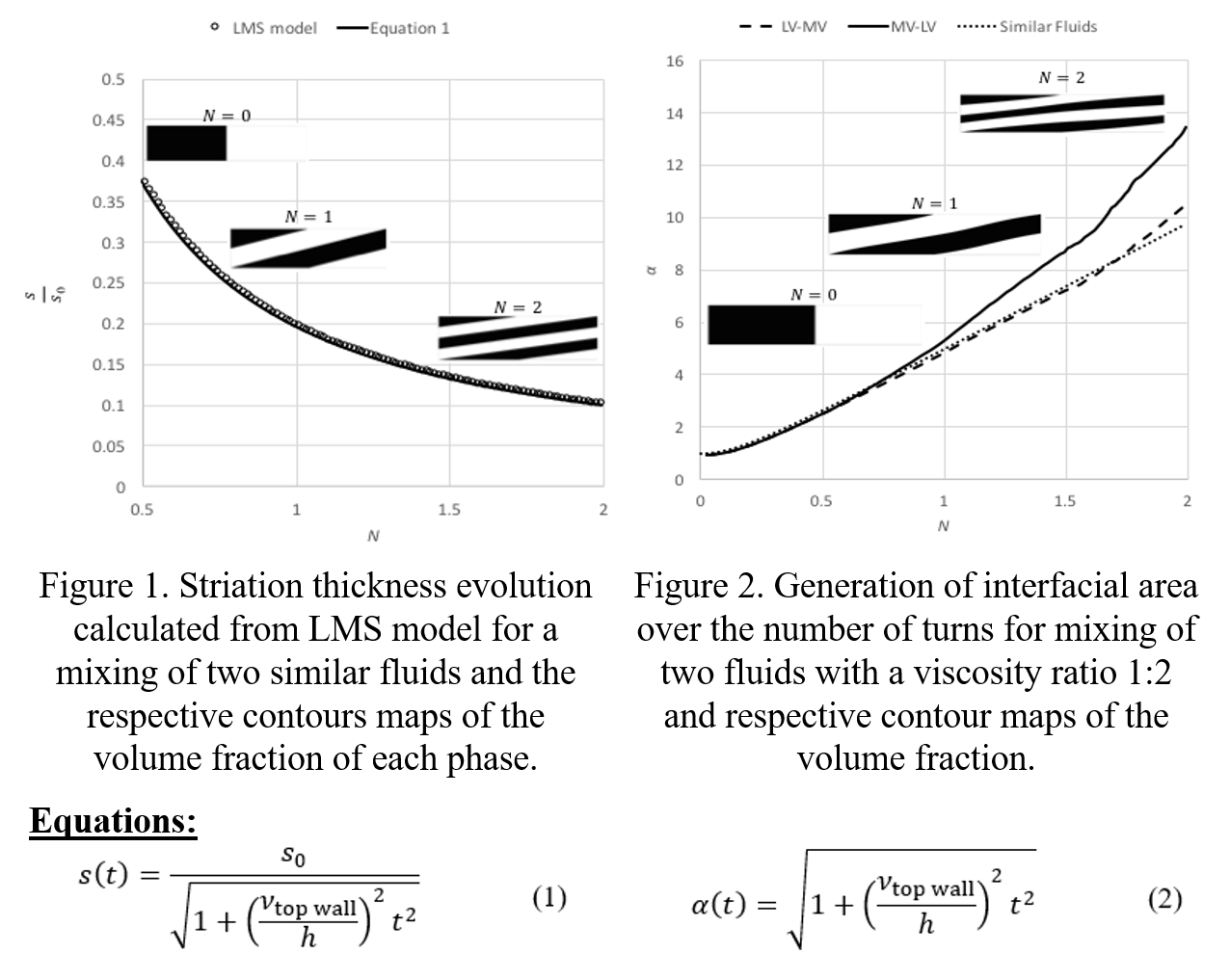
For mixing of similar fluids, the working fluids have the same density and viscosity. The initial condition of the simulation is the two fluids are side by side. Over the number of rotations, which is defined N=t/T where T is the time of one rotation, the interface between two fluids is stretched and a lamellar structure is formed. These results are in agreement with the stretching of a dye in a laminar flow reported by Mohr et al. (1957a). In that experiment, the interface that separates the dye and the main fluid is stretched in a similar way to Figure 1. This visualization enables the description of mixing from the generation of the interfacial area and the striation thickness, which is the distance between two segregated fluids (Mohr et al., 1957b; Ranz, 1979).
The evolution of interfacial area and the striation thickness decay were determined from Lagrangian Mixing Simulation (LMS) model proposed by Matos et al. (2018). Figure 1 shows the evolution of striation thickness with the number of rotations and the respective contour maps of the volume fraction of each fluid obtained from 2D CFD simulations.
A method that tracks an infinitesimal element stretched in a shear flow was implemented to calculate the striation thickness decay. For that, an incompressible fluid was considered, and the striation thickness is given by Equation 1, where so is the initial striation thickness at t=0, h is the height of the geometry. Figure 2 shows that CFD results are fitted by Equation 1. The validation of Equation 1 enables to design the operation conditions, such as, the velocity of the top plate and the number of rotations, to achieve a desired striation thickness.
From the same method used to determine Equation 1, the expression that describes the generation of interfacial area was also deducted Equation 2.
Mixing of Dissimilar Fluids
Mixing of dissimilar fluids is studied from two working fluids, which have the same density and a viscosity ratio of 1:2. The two phases are initially side by side and the stretching of the interfacial area was studied for two rotations of the top plate. The evolution of mixing scales was determined from the implementation of LMS model. Figure 2 shows the generation of interfacial area between fluids with the number of rotations and the respective contour maps of the volume fraction of each fluid obtained from 2D CFD simulations. The stretching of interfacial was determined when the most viscous fluid pushes the less viscous fluid (LV-MV) and vice versa (MV-LV). The equation that describes the interfacial area for similar fluids (Equation 2) was also plotted in Figure 2. Figure 2 shows that for N<0.5, the growth of interfaces is similar for LV-MV and MV-LV whereas, for N>0.5, the interfacial area is greater for MV-LV than for LV-MV. Figure 2 shows that, for N<2, the interface MV-LV increases, approximately, 15 times while the interface LV-MV increases 10 times.
Scale-Up of HTMD from Lab to Plant
The rotational device studied in this work is characterized by the formation of a laminar flow. This is particularly interesting in product development because it provides relevant data for the manufacturing industry. These rotational devices are easily adapted for different working conditions in the development of new materials, such as, in polyurethane production sites to make kinetic studies to be used in Reaction Injection Moulding (RIM) machines. RIM process is usually designed in pilot machines, becoming a quite-consuming time process.
The technology presented in this work can be used as a method to develop new materials at lab scale. For the design of experiments, Equation 1 and 2 can be used to predict the mixing scales achieved during the rotation of the top plate. For example, Fonte et al. (2011) reported that the mixing scales in the RIM mixing chamber are as small as s =10 μm in a period of around 100 ms in a mixing chamber with 10 mm scale range. According to Equation 1, the same mixing scale is obtaining after approximately 5 rotations of the top plate.
Conclusions
In this work, a rotational device is used to assess the evolution of mixing scales using similar fluids and fluids with a viscosity ratio of 1:2. CFD results show that quite homogeneous lamellar structures are formed, even when the viscosity ratio is 1:2. These rotational devices are proposed in this work as a method for HTDM. This method must ensure that the mixing scales generated in pilot machines are mimicked at lab scale. This is particularly useful for generating data for plant.
References
Fonte, C., Santos, R., Dias, M., Lopes, S., Lopes, J.C., 2011. Quantification of mixing in RIM using a non-diffusive two-phase flow numerical model, International Journal of Chemical Reactor Engineering,. International Journal of Chemical Reactor Engineering 9.
Matos, J., Brito, M.S.C.A., Dias, M.M., Lopes, J.C.B., Santos, R.J., 2018. Lagrangian mixing simulation and quantification of scales. Chemical Engineering Science 192, 199-210.
Mohr, W.D., Saxton, R.L., Jepson, C.H., 1957a. Mixing in Laminar-Flow Systems. Industrial and Engineering Chemistry 49, 1855-1856.
Mohr, W.D., Saxton, R.L., Jepson, C.H., 1957b. Theory of Mixing in the Single-Screw Extruder. Industrial & Engineering Chemistry 49, 1857-1862.
Ranz, W.E., 1979. Applications of a Stretch Model Diffusion, and Reaction in Laminar and Turbulent Flows. AlChE Journal 25.