(699h) Diffusion of CO2 in an Amine-Cured Epoxy Novolac Coating at HPHT Conditions: Cause of Underfilm Corrosion
AIChE Annual Meeting
2022
2022 Annual Meeting
Materials Engineering and Sciences Division
Transport Phenomena in Polymer Systems
Friday, November 18, 2022 - 10:00am to 10:15am
Despite the progress in the usage of renewable resources, fossil fuel reservoirs remain high in demand, accounting for the majority of the global energy supply. However, the oil and gas industries rely increasingly on wells and reservoirs operating at extreme conditions. Oil drilling at temperatures greater than 149 °C (300 °F) and/or pressures of 690 bars (10,000 psi) are classified as high-temperature and high-pressure (HPHT) wells [1]. Under such conditions, and in the presence of hydrocarbons, seawater, and CO2, the substrate (steel) corrosion rate increases, along with the risk of mechanical failures [2]. To avoid material degradation at HPHT, process equipment, transportation pipelines, and underground storage tanks are normally coated internally with multi-layer, epoxy-based coating systems.
Recently, a degradation study of amine-cured epoxy novolac (EN) and bisphenol F films under the combined effects of the HPHT phases suggested underfilm corrosion to be a result of the compromised coatings [3]. In particular, CO2 present in the HPHT gas phase was suspected of leading to a high corrosion rate below the coating. Apart from imparting acidity, CO2 may influence the degree and rate of degradation of EN networks via varying solubility interactions (temperature and pressure dependent), low molecular size, high mass-transfer rates, and non-polarity. In the present work, the coating gas/liquid interface phenomena, in the presence and absence of CO2, are studied using a range of analytical techniques. Furthermore, it is of interest to understand why the most severe coating degradation and associated underfilm corrosion occur at the hydrocarbon−seawater interface. Finally, the influence of CO2 on the degradation pathways of EN, leading to substrate corrosion, is mapped and discussed. The findings, additionally, have the potential to provide a much-needed supercritical CO2-resistant epoxy-based candidate to protect transport pipelines in the next-generation carbon capture and storage (CCS) domains.
Experimental
The three phases simulating the HPHT conditions are the gas phase, comprising a mixture of N2 and CO2, para-xylene representing the hydrocarbon phase, and a 3.5 wt% NaCl solution as the seawater phase. This combination of corrosive species at a reference temperature of 180 °C and a pressure of 130 bars was simulated in an enclosed batch-like reactor (autoclave) with coated steel panels placed in the chamber. Taking into consideration the application prospects of coatings in the HPHT domain, a benchmark pressure of 130 bars and a temperature of 180 °C were maintained for all experiments. In order to pinpoint the role of CO2 in the degradation of the EN system at HPHT conditions, a methodical HPHT exposure study was conducted. The comparative understanding of the nature and extent of degradation in each of the environments individually is fundamental prior to the interpretation of the combined effects of HPHT. Table 1 summarizes the environments considered. At first, the effects of the three HPHT phases were studied individually under a N2 cover (E1−E3). The second group of experiments were done by making permutations of the three HPHT phases (E4−E8). Last, in order to strategically map the role of CO2 in the degradation pathway of EN at HPHT, all the three HPHT phases combined, in the presence and absence of CO2 (E9−E10), were investigated.
Using a DEN 438 epoxy novolac resin (an average functionality of 3.6) as the base and a mixture of 3-(diethylamino)propylamine (DEAPA) and m-xylylenediamine (MXDA) adducts as curing agents, the EN coating was formulated. The novolac resin base and both the curing agents were acquired from Hexion (Spain), and the formulated EN coating was applied on a grit-blasted (surface profile of SA 2.5) mild steel substrate of dimensions 120 mm × 70 mm× 5 mm. Using a smooth natural bristle paintbrush of width 50 mm, the first coat of EN, aiming at a dry film thickness (DFT) of 75 ± 15 μm, was applied, covering both sides of the substrate and all edges of the panel.
The coating was allowed to cure for 12 h at room temperature, after which the second coat, using the same DFT, was applied. To attain further reaction between the free epoxide and hydroxyl groups, all coated samples were cured for 5 day at room temperature, followed by post-curing at 120 °C for 5 h, allowing the maximum cross-link density. The functional group stoichiometric ratio between the epoxy base and the curing agents, as well as the curing conditions for EN, were selected to be in agreement with the commercial grade formulations available for HPHT applications.
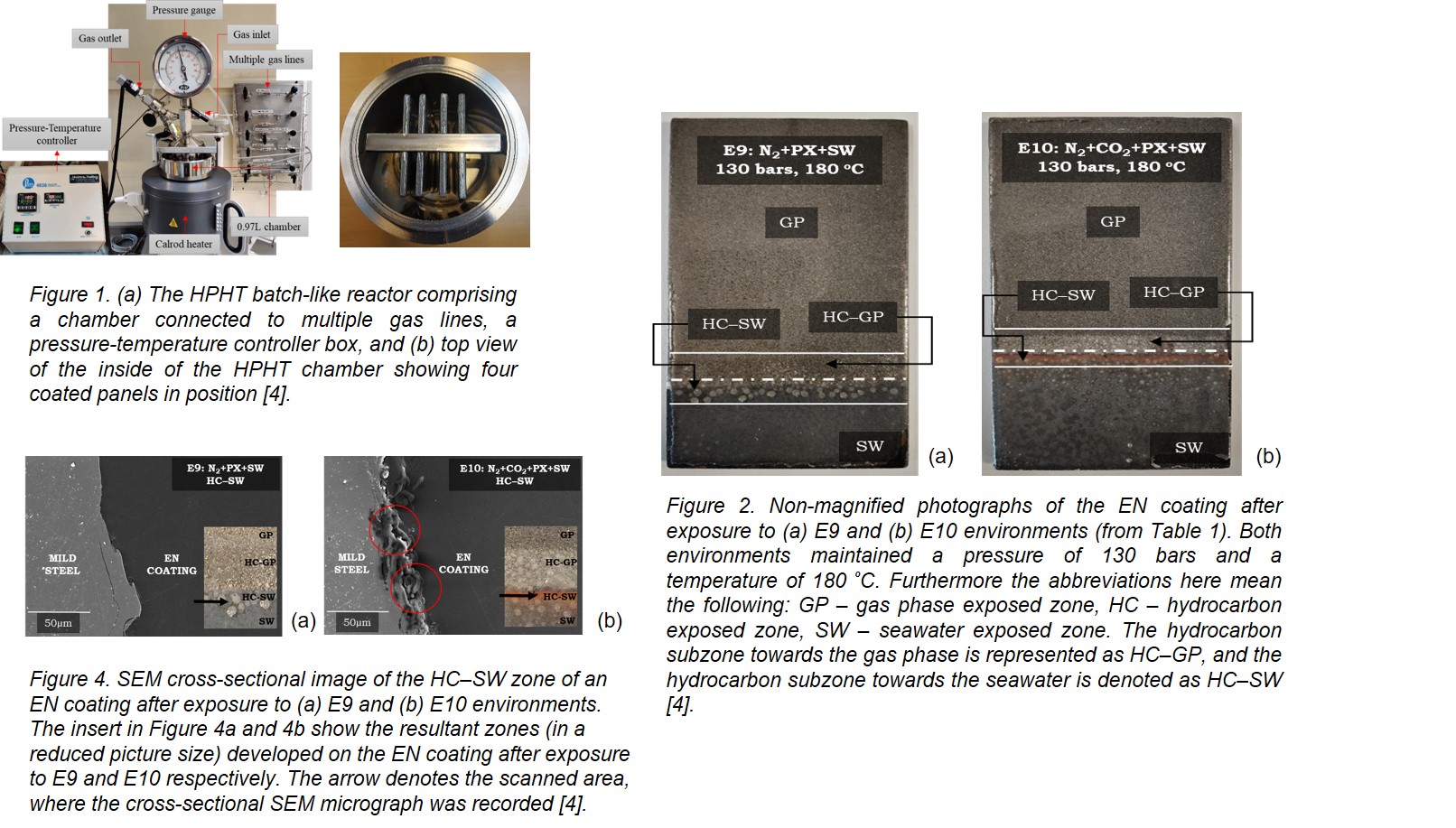
A reactor model 4621 HPHT, procured from Parr Instruments, was used to simulate the HPHT conditions. The reactor is non-stirred and capable of withstanding a temperature of 350 °C and a pressure of 180 bars. Inside the reactor chamber, four panels were placed as shown in Figure 1(a, b), respectively. The reactor walls are made of Hastelloy C-276, a nickel-chromium-molybdenum alloy, resistant to extreme corrosive environments. The setup is connected to multiple gas lines (high-pressure N2 and CO2), a pressure and temperature controller box, a heater (tubular heating element that converts electricity into heat via Joule heating for uniform heating), an external pressure gauge, and safety valves.
Results & Discussion
In the presentation, the epoxy novolac coating interactions with the three HPHT phases individually will be discussed. Effect of the phases on the coating surface (optical microscopy studies), on the crosslinking (Tg measurements), chemical interactions if any (FTIR analysis), and the adhesion properties between the coating and the steel interface at each of the zones will be communicated. In the following section, only the most important findings from the synergistic action of HPHT phases are summarized. When all the three HPHT phases (i.e. gas, hydrocarbon, and seawater) are present (E9 and E10 in Figure 2), the EN coating showed three distinct zones.
For both E9 and E10, the resultant HC zone exhibit two subzones: one towards the gas phase, termed as the HC–GP zone, and the other towards the seawater phase, named the HC–SW zone. For E9 (HPHT gas phase in the absence of CO2), the HC–GP zone showed a mild discoloration, and the HC–SW zone exhibited large blisters (3 to 5 mm in size) and surface voids (Figure 2a). On the contrary, the HC–GP zone for E10 displayed formation of blisters, and the HC–SW zone showed a red-colored, dense iron oxide accumulation on the surface (Figure 2b). Moreover, the blisters formed at the HC–SW zone of E10 were relatively small (1 to 2 mm in size). Due to the presence of CO2 in E10, different sorption kinetics and transport rates (water uptake) influenced the pressure build up leading to blisters smaller in size than for E9. The SW zone under conditions of E9 (Figure 2a) was relatively intact with no significant surface inhomogeneity. However, for E10 (Figure 2b), the severity of degradation was more pronounced in the form of tiny blisters (less than 1 mm in size).
To confirm the origin of the corrosion products and their dependency on the presence of CO2, SEM micrographs of the cross-section of EN at its HC–SW for both E9 and E10 zone were recorded. The cross-sectional SEM image of the steel-coating interface at the HC–SW zone of the EN coating after exposure to E10 (Figure 4b) showed accumulation of corrosion products (marked by red circles). Figure 4b is the cross-sectional SEM micrograph of the steel-coating interface at the HC–SW zone of the EN system after exposure to E9 (HPHT gas phase without CO2) showing unaffected steel with absolutely no defects or corrosion products.
Conclusions
The findings from the present study help the formulation specialists to design a superior coating formulation for HPHT applications. Initiation of the hydrocarbon associated softening interaction with the EN was the main culprit as far as the degradation pathway was concenrned, which aggravated the diffusion of CO2 and seawater ions into the EN network and triggered underfilm corrosion. At HPHT conditions devoid of CO2, the same showed only blisters, but no underfilm corrosion. The results demonstrate that para-xylene, representing the hydrocarbon phase at HPHT, initiated glass-transition temperature depression with subsequent softening of the EN network. This allowed the dissolved CO2 gas to diffuse into the EN network, thereby generating pinholes at the coating surface. The pinholes further aided the seawater ions at its hydrocarbon−seawater interface to diffuse into the EN network to the steel substrate, imposing underfilm corrosion. The findings are of high relevance to design superior epoxy-based coatings not only for the petroleum industry but also for the protection of transport pipelines and process equipment in the next-generation carbon capture and storage technologies. To sustain the extreme HPHT applications, one hypothesis is to introduce stable inorganic functional groups (e.g., polymers with siloxane functional groups) into the epoxy novolac networks, which may help resist the aromatic hydrocarbon softening interactions and oppose the diffusion of HPHT corrosive species.