
Sections
Pressure measurement instrumentation is a critical part of plant infrastructure. Understanding and employing pressure transmitter best practices will maximize the life of these key plant assets.
Pressure transmitters are among the most common measurement devices in the chemical process industries (CPI). These devices are critical to ensuring efficient operation, optimized process control, and process safety. Understanding how to specify, install, and maintain pressure transmitters can provide a solid foundation for extending the useful life of these products in even the toughest process environments.
This article provides tips for selecting pressure transmitters, such as identifying the right materials, selecting the proper range, and fitting the technology to primary elements to infer flow and level measurements. Additionally, this article discusses appropriate installation techniques, including impulse piping orientation as a function of service, mechanical mounting considerations, and proper manifold valving procedures during sensor calibration. Finally, it will discuss manifold valving during service and review one of the most important considerations in maintaining the health of a pressure transmitter: calibration frequency.
Identifying transmitter specifications
When choosing pressure transmitters for process measurements, it is necessary to compare the specific process parameters to a transmitter’s specifications to ensure robust performance and safety. Improving the useful life of a pressure transmitter starts with selecting a compatible transmitter for the application. Manufacturers of process instrumentation are challenged to provide a vast selection of options for their products to meet requirements that vary widely around the world and across industries, from agriculture to wastewater and everything in between. Pressure transmitter model codes identify each product and offer enough variety that a single product model structure can offer millions of possible combinations. When choosing the best topics for consideration regarding pressure transmitter specification, a good place to start is common sources of failure on returned products. The next sections review some of these common sources of failure.
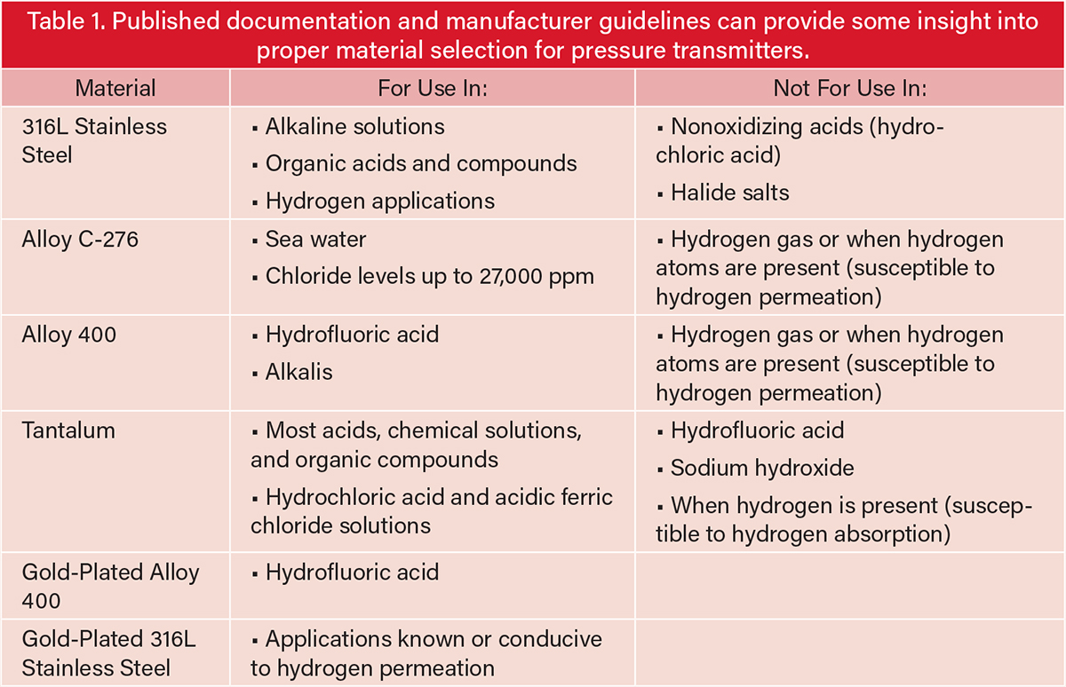
Material selection. Even a basic review of published documentation such as manufacturer’s material selection guides, Schweitzer’s Corrosion Resistance Tables, or the NACE Corrosion Survey Database can provide tremendous insight into proper material selection for a pressure transmitter based on the process fluid and service temperatures that the device will encounter (1). Cross-referencing one source against another can help further solidify the selection of an appropriate material. There are no guarantees that process fluid composition will exactly match the conditions cited in the references used to establish expectations for corrosion resistance in each application, so users are often left with only suggestions for proper material selection, as demonstrated in Table 1.
Pressure range selection. Selecting the right pressure range is important for optimizing performance and preventing damage from overpressure. Gauge and absolute pressure transmitters are typically designed to have a maximum working pressure that matches the sensor limit for the device. For example, a process pipe with ASME B16.5 Class 300 flanges constructed of Group 2.2 material will support up to 720 psig at temperatures up to 100°F. To meet and exceed this limitation, a pressure transmitter installed on that line would be fitted with a sensor with a maximum working pressure of 800 psig that accurately measures any pressure the line is designed to accommodate. Accuracy at lower operating pressures can be improved by using a turndown factor — or the ratio of maximum allowable calibrated span to minimum allowable span — of up to 200:1 for factory calibrations to optimize performance.
Differential pressure transmitters are more complicated because they measure very small differential pressures at high process static pressures. The first step is to understand the magnitude of the differential pressure generated in the application. Next, the maximum working pressure of the transmitter must be verified to ensure that the transmitter can meet the static pressure design limitations at the installation point.
As an example, consider a typical orifice plate flow measurement point, a common flow measuring device that induces a pressure drop. In this case, the orifice plate is installed in a flange union and will generate 100 inH2O at 68°F of differential pressure at the design flow condition. This specific flange union will support up to 1,440 psig at temperatures up to 100°F. For a proper selection, the pressure transmitter installed at this flange union should have a differential pressure sensor that will measure 100 inH2O at 68°F with the desired accuracy and still be capable of supporting a maximum working pressure that exceeds 1,440 psig.
As another consideration, it is vital in flow applications to select a differential pressure range that exceeds the differential pressure at the design flowrate by at least a factor of 1.25. This allows for variation in process flow conditions that may cause the differential pressure sensor to saturate during upset conditions at high flowrates. Simple flowrate extraction from differential pressure relies on a square root relationship that leads to an increased risk of sensor saturation upon flowrate deviations beyond design parameters.
Integrated flowmeters simplify specification. Complications that arise from inferring flowrate from differential pressure are made worse when considering the hardware required to connect the pressure transmitter to the primary element. In traditional installations, numerous pieces of hardware, such as impulse lines, elbows, tees, and isolation valves, are required to connect the transmitter and the primary element (Figure 1). These components are necessary to transfer pressure from the process line to the measurement point and enable key functions such as pressure equalization for zero adjustments and isolation for blowdowns and maintenance tasks. This complexity is further exacerbated by fully compensated flowrate measurements where differential pressure, static pressure, and temperature are all measured to dynamically compensate for all process variables to provide an accurate mass flowrate measurement.
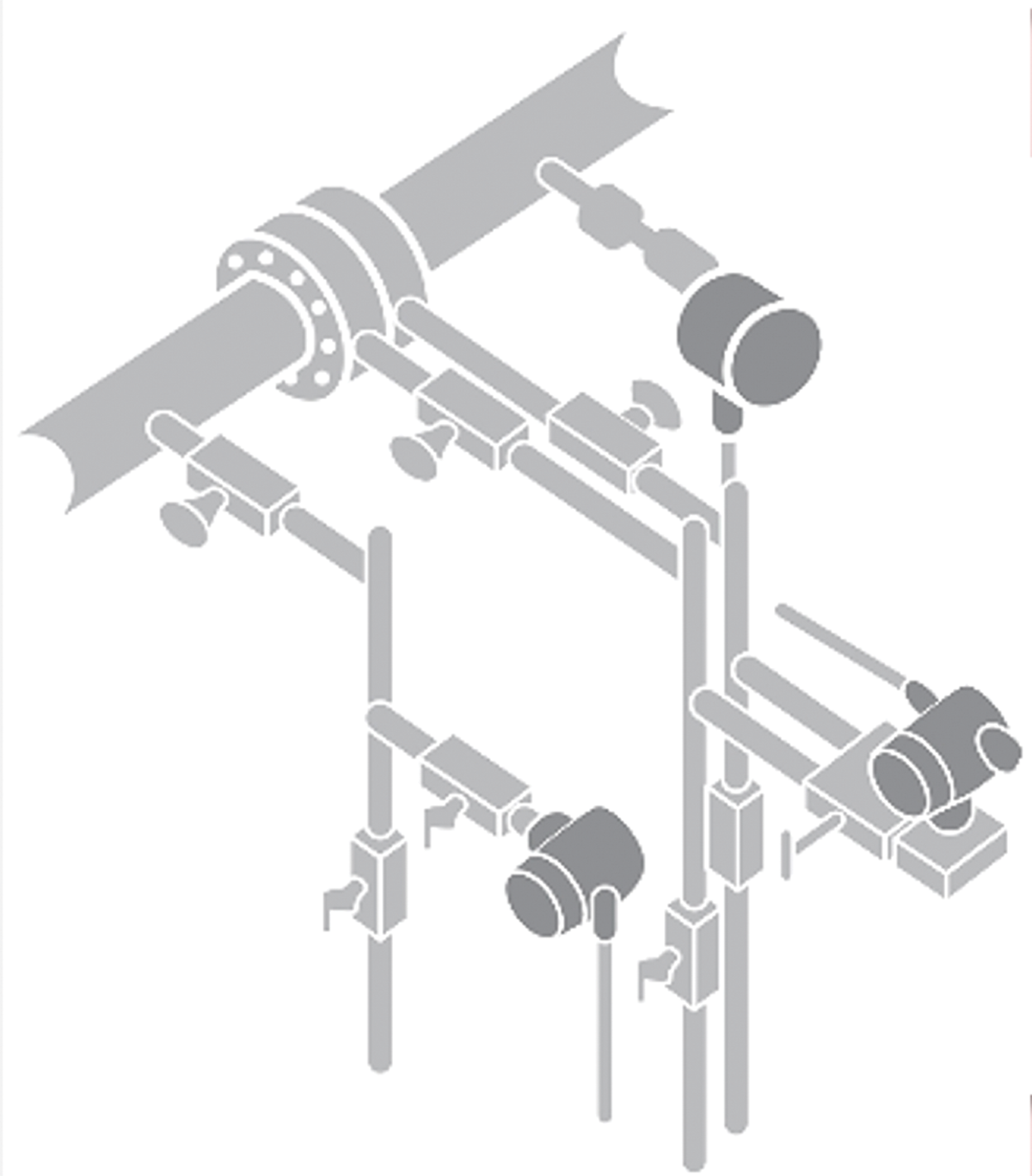
▲Figure 1. In a traditional installation, each measurement, including static pressure, differential pressure, and temperature, is made at different points near the primary element. This is done using independent connection systems to transfer the process pressure to the instrument.
Integrated differential pressure flowrate measurements provide the primary element, connection hardware, manifold, and differential pressure measurement required to make an accurate flowrate measurement without having to specify dozens of separate components or ensure that they fit the given application (Figure 2). Multivariable transmitters provide differential pressure, static pressure, and process temperature measurement in a single transmitter, along with a built-in flow computer that can compensate for all dynamic variables to provide high-accuracy mass and energy flowrate output. These integrated differential pressure flowmeter solutions simplify complex traditional installations that can be riddled with specification inconsistencies and errors.
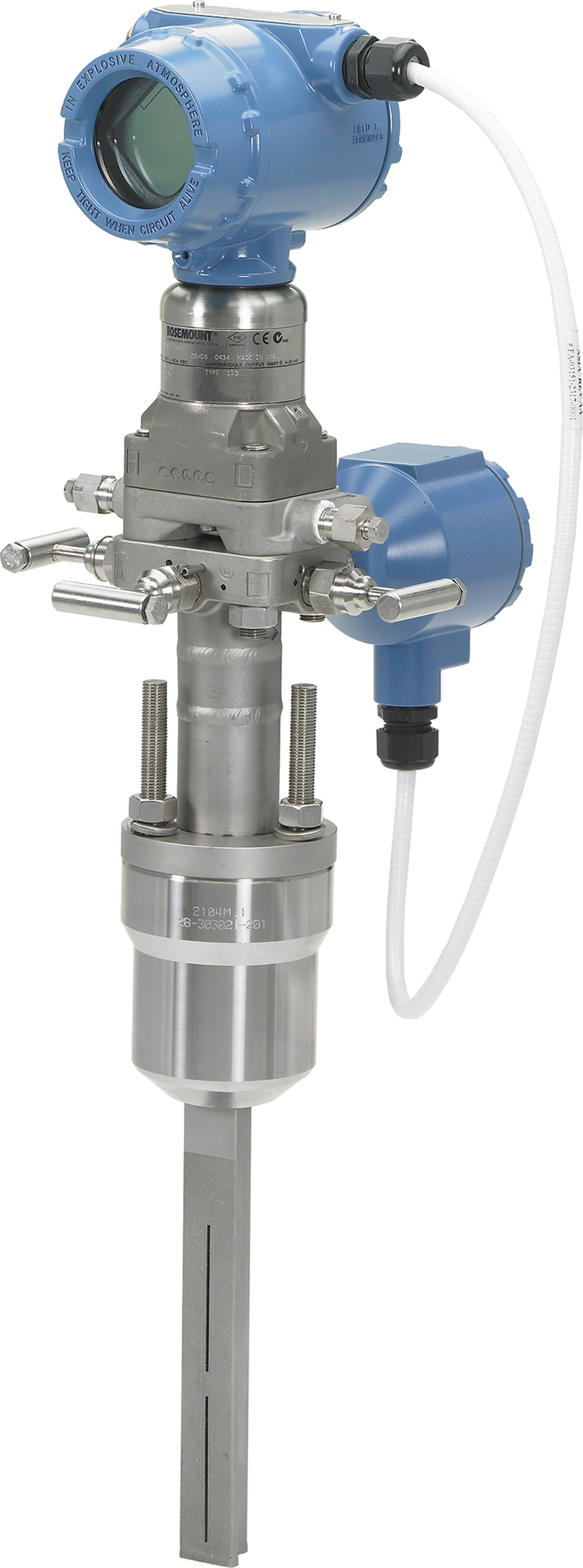
▲Figure 2. An integrated flowmeter, like the Rosemount 3051SFA integrated Annubar flowmeter, directly mounts the measurement device to the primary element inside the process line. This type of flowmeter includes a manifold to enable maintenance and calibration of the instrument. The measurement device senses static pressure, differential pressure, and process temperature through a single pipe penetration.
Similarly, level measurements based on differential pressure often require hardware to connect the transmitter to the tank where the level is measured. Pressurized tanks introduce challenges as they require an assembly that can withstand the tank’s design pressure, make the differential pressure measurement needed to infer a level measurement, and be mechanically fitted to process flange connections available on the tank. Remote seal systems, which use a flexible membrane to translate pressure through capillary tubes to a pressure sensor, are often used to protect sensors, but the capillary tubes introduce error when the ambient temperature varies at the installation point. In the case of tall tanks with a long distance between taps and larger measured differential pressures, electronic remote seals can be used to measure static pressure at the installation points and transmit a single level signal, calculated by the difference in measured static pressures, back to the host.
Specifying both flowrate and level measurements based on a pressure measurement is greatly simplified with sizing tools available online that gather process condition data. These sizing tools can also transmit data concerning piping and tank materials and dimensions, enabling the user to compare available technologies. Performance reports that show the expected uncertainty of key measurements based on process conditions and selected measurements help the user identify the best technology for their specific application.
Installation considerations
The first consideration for properly mounting a pressure transmitter is the process fluid that is being measured. Installation best practices vary depending on whether the fluid is a gas, liquid, or steam. In all cases, the orientation of the transmitter relative to the pipe or vessel is an essential consideration in maximizing the performance and useful life of the device.
Gas applications. For gas applications, keeping the transmitter above the process is vital. This will allow any condensate that may form or moisture that is entrained in the gas to run back into the line or vessel, thus avoiding any accumulation at the transmitter interface. It is important to slope impulse lines, which transfer pressure from the process line to the pressure transmitter, to ensure that the liquid will flow in the direction of the process, away from the transmitter (Figure 3). A trap can also be installed to capture excessive liquid that may form in more challenging condensing vapor applications so that the accumulated liquid can be blown out at regular service intervals. Avoiding liquid on the transmitter interface prevents the formation of tide lines of precipitated solids that can lead to corrosion and plugging at the pressure measurement point.
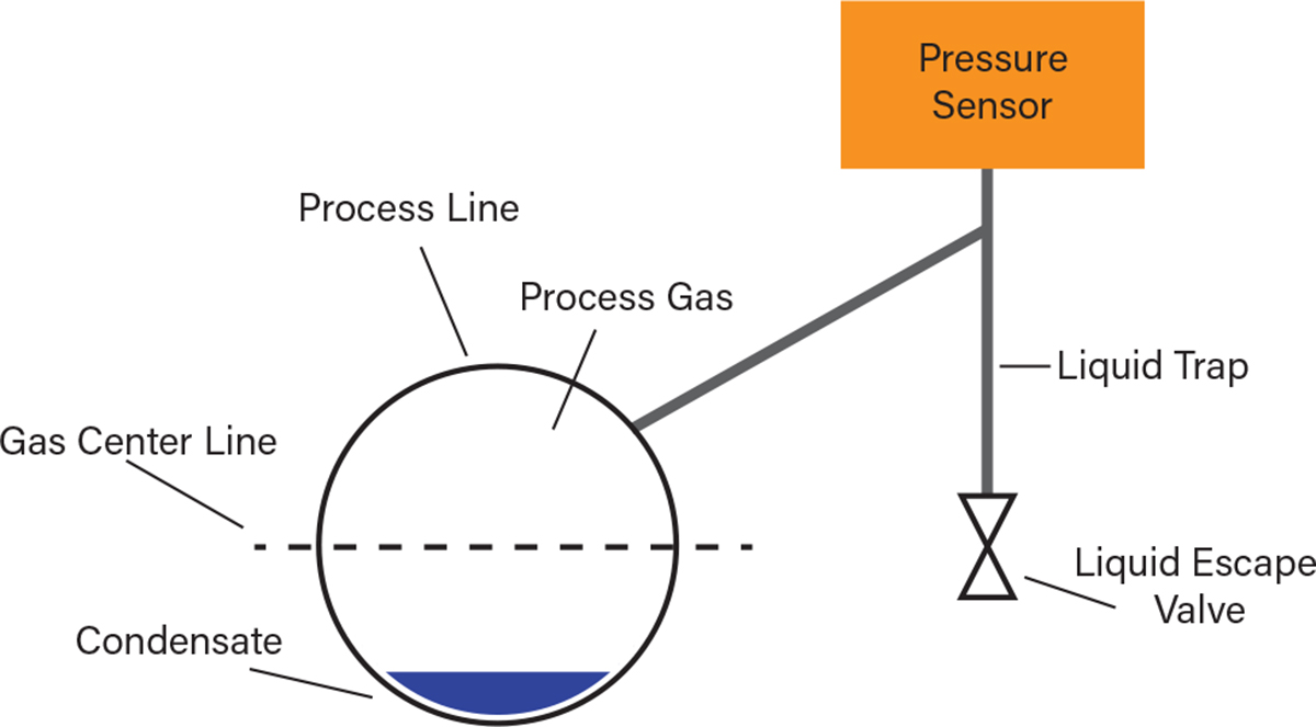
▲Figure 3. For gas applications, the transmitter must be installed above the process. Doing so forces any condensate that may form or moisture that is entrained in the gas to run back into the line or vessel. This avoids any accumulation at the transmitter interface that could lead to corrosion or inaccurate readings.
Liquid applications. For liquid applications, it is important to keep the transmitter below the process (Figure 4). This will allow any entrained gas that may enter the transmitter connection to return to the process line rather than accumulate at the transmitter interface. It is important to slope impulse lines to ensure that the gas will flow in the direction of the process, away from the transmitter. A trap can also be installed to capture excessive gas that may form in more challenging liquid/vapor equilibrium applications so that the accumulated vapor can be blown out at regular service intervals. Avoiding gas on the transmitter interface prevents the formation of vapor pockets at the measurement interface, which can result in unsteady and inaccurate pressure measurement. It is also important to note that impulse lines should not be connected at the bottom dead center of the pipe. Any solids running along the bottom of the pipe can collect at the impulse line interface and lead to plugging.
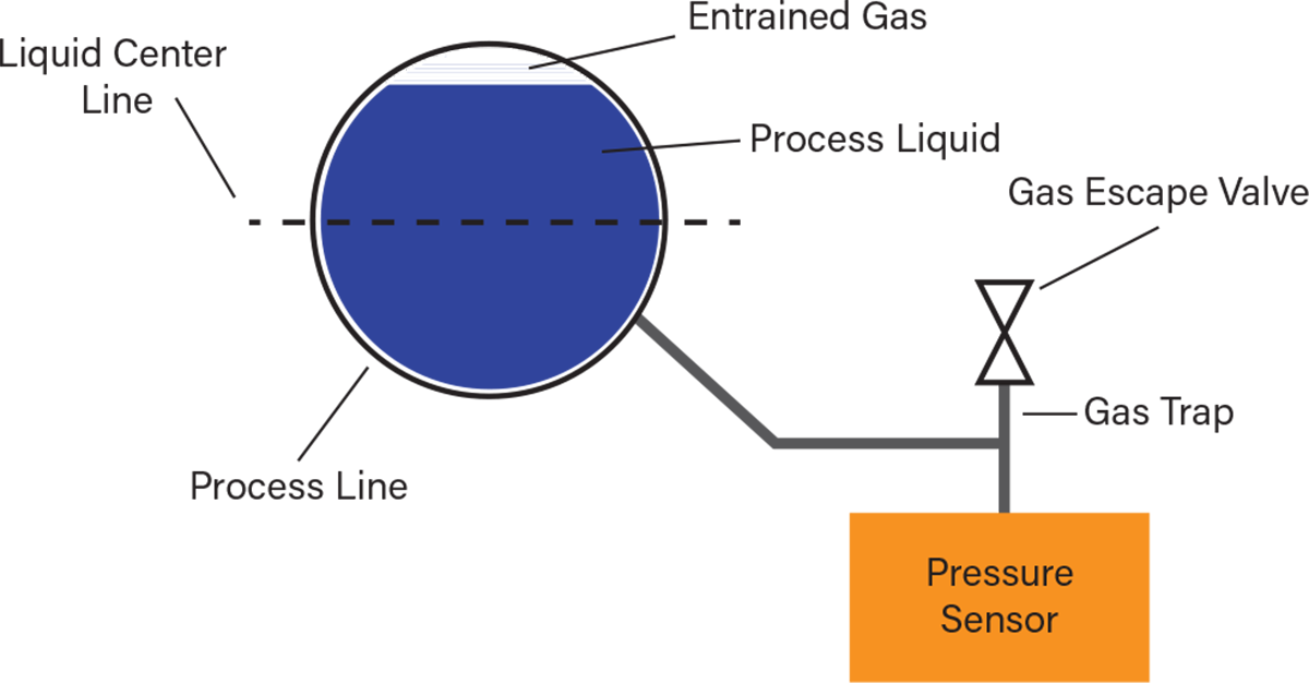
▲Figure 4. For liquid applications, the transmitter must be installed below the process. Doing so will force any entrained gas that may enter the transmitter connection to return to the process line rather than accumulate at the transmitter interface. This avoids vapor pockets forming at the measurement interface, which could lead to inaccurate pressure measurements.
Steam applications. Steam applications are often considered the most complicated installations to handle due to the inherent liquid/vapor equilibrium that occurs between the process pipe and the pressure transmitter. Steam — and condensing vapors in general — are unique in that instruments can be mounted on the top or the bottom of the pipe depending on how the instrument is connected.
With the right installation considerations, either approach is viable. In the most basic consideration, mounting from the top or the bottom of the pipe will require specific installation requirements to manage the liquid condensate accumulation that is essential to protect the transmitter from extreme process temperature and the damage that can be done when exposed to live steam. In the following sections, integrated flowmeters, which are installed directly to the process line, are referred to as direct-mount installations. Traditional flowmeters, which use impulse lines, elbows, and tees to separate the measurement instrumentation from the process line, are referred to as remote-mount installations.
Top mount. For top-mount steam installations, a remote-mount installation is recommended, and should include impulse tubing, isolation valves, fill tees, drop legs, blowdown valves, and an equalization manifold on the pressure transmitter (Figure 5). High- and low-pressure connection drops are used to maintain a wet leg of condensate to protect the transmitter from overheating. Any liquid that accumulates between the transmitter and the process on the high- and low-pressure side must be set with the same liquid head elevation to avoid an induced differential pressure at the transmitter that cannot be zeroed out without isolating and venting the head pressure from each leg. Keeping high and low drops at the same elevation ensures that the measured differential pressure is generated by the primary element only, not by a difference in liquid column height above the high and low differential pressure sensors. It is beneficial to periodically perform blowdowns by blowing steam through the drop legs to purge any accumulated solids or precipitate that may form and lead to plugging.
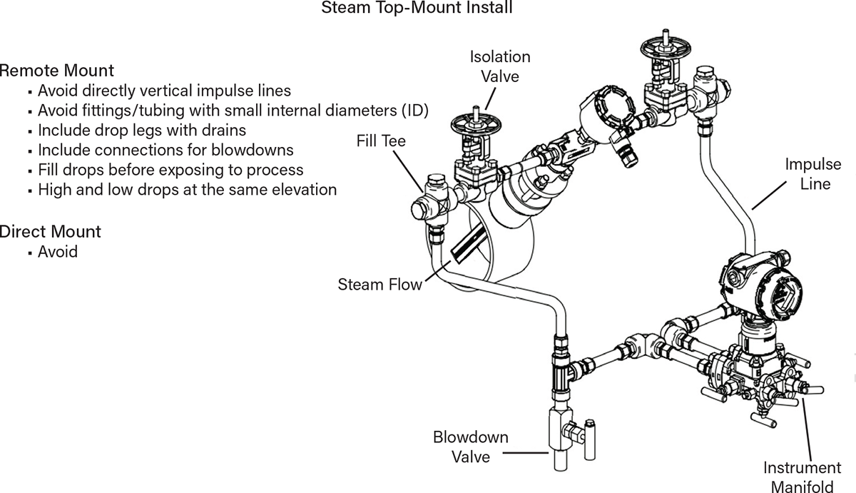
▲Figure 5. For top-mount installations in steam applications, it is best to use a remote mount and avoid direct mounts because the process temperatures can often exceed the sensor’s specified limits. Additionally, keeping high and low drops at the same elevation ensures that the measured differential pressure is only generated by the primary element and not by a difference in liquid column height above the high and low differential pressure sensors.
Tubing and fittings with small internal diameters can increase the risk of plugging and may lead to the formation of a meniscus that suspends liquid in upward legs where condensate is intended to return to the process line. These suspended liquids can lead to erratic or erroneous differential pressure measurements.
Direct mounting is not recommended in top-mount steam installations because the measurement device can be exposed to temperatures that exceed specified limits.
Bottom mount. For bottom-mount steam installations, either a remote-mount or a direct-mount configuration can be installed (Figure 6). However, tubing and fittings with small inner diameters should be avoided when choosing a remote-mount configuration. It is particularly important to avoid mounting directly onto the bottom of the pipe where solids and precipitate can accumulate and lead to plugging.
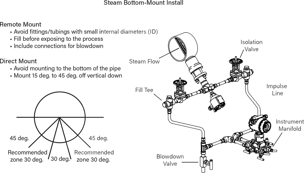
▲Figure 6. For bottom-mount installs in steam applications, many of the rules for remote top-mounts apply to bottom mounts as well, including avoiding fittings/tubing with small internal diameters (ID), filling with fluid before exposing the sensor to process pressure, and including connections for blowdowns. Direct mounts are acceptable with bottom-mount installs, but they should not be connected at the bottom of the pipe and should be angled 15–45 deg. off of vertical.
Mechanical mounting considerations. Most industrial pressure transmitters are rated to withstand 3G vibration; however, isolating transmitters from vibration with proper mounting will ensure extended service life against fatigue-induced failures. It is important to understand the source of vibration and to identify installation points that minimize exposure to vibration. The best approach is to mount instrumentation to rigid structures that are not vibrating.
The final installation consideration pertains to sealing the transmitter electronics from the environment. First, ensure transmitter covers are tightened fully with metal-to-metal contact between the transmitter housing and the cover so that the O-ring material is no longer visible. Next, seal any unused transmitter conduit openings with threaded plugs that are properly rated for hazardous locations. Finally, seal electronic connections with sealants or barriers to prevent water ingress into the conduit (Figure 7). Conduit or wiring should be in a physical orientation that traps and isolates accumulated moisture from the transmitter housing.
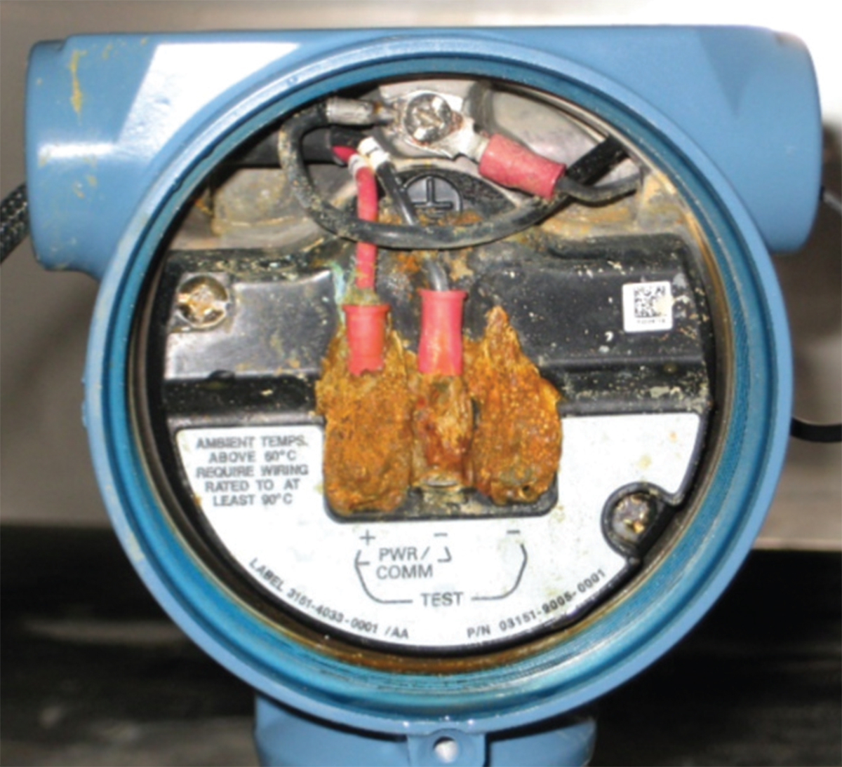
▲Figure 7. Neglecting to include conduit entry seals can lead to moisture entering the sensor’s housing. When left uncorrected, the terminals in a housing corrode, leading to mechanical failure and inaccuracy.
Improving data by sensor trimming
Unlike absolute pressure sensors, differential pressure transmitters need to be zero-trimmed, or calibrated to erase zero-drift, to ensure a zero pressure reading when the high- and low-pressure sensors are exposed to the same pressure after installation. This is necessary to eliminate mechanical mounting effects that can offset the pressure reading, especially when the differential pressure is very small, the static pressure is high, or both.
Differential pressure measurement applications commonly use a three-valve manifold; this configuration has a valve on the high-pressure side and a second valve on the low-pressure side, as well as an equalize valve between the high- and low-pressure lines. These valves are common in differential pressure measurement applications, as they allow the high-pressure side to be separated from the low-pressure side by the equalize valve. Under normal operation, a differential pressure transmitter with a three-valve manifold has a closed equalize valve.
To properly zero this transmitter, first close the low side isolation and then open the equalize valve (Figure 8). This will apply the static pressure from the high side process connection to both the high and low isolators. A zero performed at this condition will ensure a robust zero at-line pressure to eliminate both mounting and static pressure effects at zero.
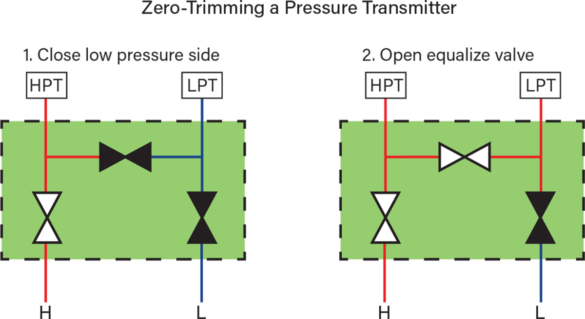
▲Figure 8. Properly zero trimming a differential pressure transmitter will ensure a zero pressure reading is recorded when the high- and low-pressure sensors are exposed to the same pressure. In this diagram of a three-valve manifold, the valve icons are black to indicate the closed position and white to indicate the open position. The “H” represents the high-pressure side of the manifold and the “L” represents the low-pressure side. The readings from the high-pressure transmitter (HPT) and the low-pressure transmitter (LPT) are used to calculate the differential pressure.
Span trims that adjust the transmitter output to match a pressure source applied to the high side of the transmitter should be avoided. Factory calibrations ensure that reference accuracies are maintained after the device is commissioned and remain intact with zero-trims that provide an offset adjustment (compared to the slope adjustment made by a span trim that will overwrite the factory calibration). The next section includes more information on calibration best practices.
Maintenance best practices
The final consideration to extend the life of pressure transmitters is proper maintenance. When manifolds are used to isolate the transmitter from a process, it is important to understand the correct valving procedures when putting a transmitter into and out of service.
Manifold valving procedures for commissioning and decommissioning. Putting a transmitter into service involves a four-step process that protects the transmitter from overpressure on the differential pressure sensor, especially in high static pressure installations (Figure 9):
- Begin with the high and low side isolation valves closed during process startup. Then, open the equalize valve.
- Open the high-pressure valve slowly. This will expose the high and the low side process isolators to the line’s static pressure. This will keep the differential pressure at or near zero while the device is exposed to line pressure.
- Close the equalize valve to trap the static pressure on the low side while maintaining a near-zero differential pressure.
- Finally, open the low-pressure isolation valve to expose the low side sensor to the process pressure.

▲Figure 9. Commissioning a transmitter involves a four-step process. When performed correctly, this method protects the transmitter from overpressure on the differential pressure sensor, especially in high static pressure installations.
Following this process in reverse will allow the transmitter to once again be isolated from the process pressure and vented for decommissioning without exposing the differential pressure sensor to an extreme overpressure event (Figure 10).
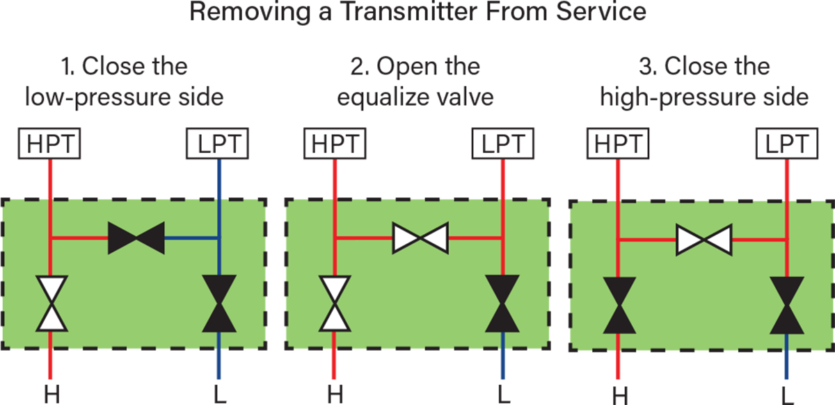
▲Figure 10. The process of removing a transmitter from service is the reverse of the installation process without the initial step of opening the equalize valve. This method prevents the sensor from being exposed to extreme overpressure.
Calibration frequency. Factory calibrations utilize the highest accuracy sources available and are performed under controlled ambient temperatures. These calibrations are the most reliable way to ensure that field devices perform equal to or better than published performance specifications. The best practice for device verification upon installation is to perform a zero-trim using the proper manifold valving procedures to remove mounting effects. Span trims should be avoided, and users should order and leverage a factory calibration certification document wherever possible. The factory calibration can serve as the installed device calibration and avoids span trims in the field, which can do more harm than good (2).
After installation, calibration frequency requirements are best established by using conservative performance requirements to set the timing for routine verifications. Pressure verifications should include a transmitter zero-trim to eliminate any zero-drift that may have occurred since installation. Span pressure can then be applied using a reliable, accurate source, and the output should be compared to the expected value with a tolerance that allows for error contribution from both the source and the transmitter. This error estimation should be calculated using a root sum of squares approach to estimate the combined uncertainty effect of independent variables. Still, only when the device output is determined to be outside of the expected reading should a span trim be considered. Before performing a span trim, the calibration source reference accuracy should be confirmed to be at least four times better than the transmitter reference accuracy. Additionally, the span trim should only be performed at a nominal, stable ambient temperature. The time between installation and the first required span trim provides a calibration interval that can be used moving forward.
Calculating expected calibration intervals from published specifications to estimate the timing for the first verification is a five-step process detailed in Ref. 3:
- Establish the performance requirements.
- Define the operating conditions.
- Calculate the total probable error for the device in installed conditions.
- Identify the stability specifications for the device.
- Calculate the calibration interval.
High-performance transmitters can extend calibration intervals and deliver calibration maintenance cost savings that offset the initial purchase price increase. The impact of performance class on calibration interval is demonstrated in Ref. 3 through a sample calculation.
In closing
Pressure sensors are vital to the efficiency and safety of many processes. Therefore, ensuring that a sensor’s specifications are compatible with the specific needs of a process are just as crucial to the accuracy and longevity of a transmitter. Knowing the best practices for pressure sensor installation and maintenance can greatly extend the life of a pressure sensor, helping to save significant time and cost.
Literature Cited
- Schweitzer, P., “Corrosion Data Survey,” National Association of Corrosion Engineers, Houston, TX (2004).
- Buckbee, G., “How to Improve Performance of Process Control Assets,” Intech, http://www.isa.org/FileStore/Intech/WhitePaper/WPAssetPerf2011.pdf (accessed Oct. 14, 2011).
- Emerson Electric Co., “How to Calculate Pressure Transmitter Calibration Intervals,” Emerson, St. Louis, MO, https://www.emerson.com/documents/automation/technical-note-how-to-calculate-pressure-transmitter-calibration-intervals-en-7432098.pdf (Mar. 2021).

Copyright Permissions
Would you like to reuse content from CEP Magazine? It’s easy to request permission to reuse content. Simply click here to connect instantly to licensing services, where you can choose from a list of options regarding how you would like to reuse the desired content and complete the transaction.