
This article is based on a paper presented at the AIChE Spring Meeting, Ethylene Producers’ Conference, April 2016.
Centrifugal compressors are used in ethylene plants for cracked-gas compression and refrigeration services. This article describes the basic design and operation of these compressors.
The mechanical engineers who design the centrifugal compressors within ethylene plants are often disconnected from the process engineers who specify the pressure, temperature, and flow requirements. This article provides an overview of the centrifugal compressors used in ethylene plants for a process-oriented audience. It describes the operation of these compressors, and clarifies some of the typical industry jargon, to help increase understanding across disciplines and reduce miscommunications between process engineers and equipment designers.
Centrifugal compressor overview
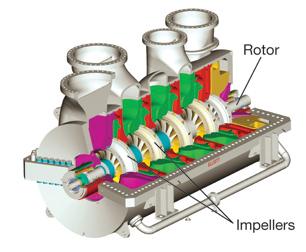
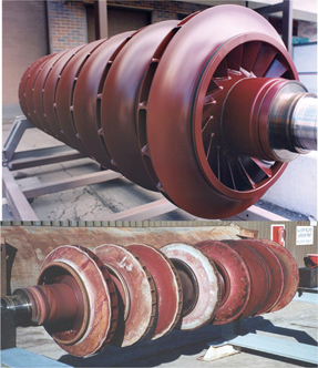
▲Figure 1. Centrifugal gas compressors are dynamic machines that impart kinetic energy into a gas by accelerating the gas through impellers. They recover that energy as pressure within the diffusers. Image courtesy of Elliot Group.
Centrifugal gas compressors are dynamic machines that impart kinetic energy to process gas by accelerating the gas through impellers (Figure 1). The gas enters the impeller with little or no radial velocity. The impeller imparts work to the gas by accelerating the gas from the eye of the impeller out toward the tip. The gas exits with a radial velocity equal to the tip velocity of the impeller. It then decelerates in the diffuser, and that energy is converted into pressure. The gas is redirected to the next impeller in the return channel, or collected in a volute and discharged through the discharge nozzle. From single-stage air blowers to 100-MW multibody cracked-gas compressors, the principle of operation is the same.
Centrifugal compressors are employed in ethylene plants because they can handle very large volumes and are very robust, allowing for continuous operation in critical services.
For the purpose of this discussion, the centrifugal compressor can be broken down into two sets of components: process and mechanical. The process components are those that are in direct contact with the gas — the rotor (with its impellers), the diaphragms (which contain diffusers), return bends, and volutes. These parts do the work required by the process. The mechanical components are the pressure-containing and support systems of the compressor — the casing, nozzles, end walls, journal and thrust bearings, and seals. These parts allow the process components to do the required work safely and reliably.
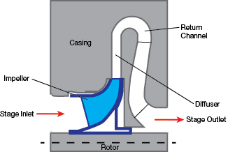
▲Figure 2. A single compressor stage consists of an impeller, diffuser, and return channel (or volute).
The process components make up the compressor flow path from inlet to discharge. The most important parts of the flow path are the compressor stages. When compressor designers discuss a compressor stage, they are referring to a single impeller and diffuser arrangement (Figure 2). In multistage compressors, multiple compressor stages are placed in series to achieve the desired pressure increase to meet the process requirement.
Process engineers, however, typically refer to a single compression requirement as a process stage. This can lead to confusion. A multistage centrifugal compressor may require many impellers and diffusers between the inlet and the discharge flange to meet the head requirement of the process designer’s stage. A common example is a multistage cracked-gas compressor — a three-stage compressor on the process flow diagram may have as many as 12 compressor stages.
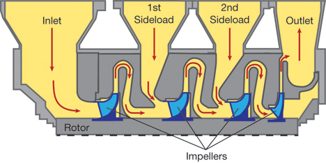
▲Figure 3. Although this simplified compressor has three process stages, it has four compressor stages.
You can distinguish between a process stage and a compressor stage by remembering that a flange-to-flange process is a process stage. For example, a C3 refrigeration compressor with two sideloads has three process stages — inlet to sideload 1, sideload 1 to sideload 2, and sideload 2 to discharge (Figure 3). Each of these process stages may have multiple compressor stages.
Surge
No discussion about centrifugal compressors can take place without mentioning surge. Entire graduate-level courses could be taught on surge, surge detection, mediation, and antisurge controls. API 617 (1) defines surge as “… a characteristic behavior of an axial or centrifugal compressor that can occur when inlet flow is reduced such that the head developed by the compressor is insufficient to overcome the pressure at the discharge of the compressor. Once surge occurs, the output pressure of the compressor is drastically reduced, resulting in flow reversal within the compressor.”
On a typical compressor curve, the surge point is typically set as the point at which the head no longer rises with a reduction in volumetric flow. When the compressor curve becomes flat, a compressor may not be in surge, but care must be taken to prevent sudden shifts into surge. Surge can be very destructive to centrifugal compressors. Thus, elaborate control systems with antisurge recycle valves are put in place to prevent damaging surges during operation.
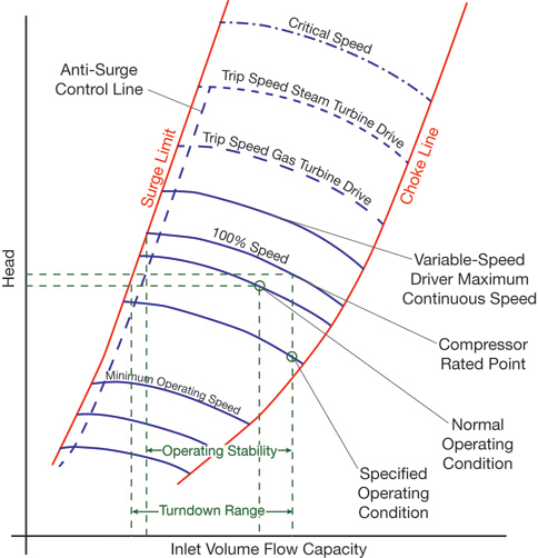
▲Figure 4. A compressor curve shows surge and stonewall (or choke) points. Source: (1).
As surge defines the minimum flow side of the compressor curve, stonewall (or choke) defines the high flow side. The amount of work that can be applied to the gas is limited by the ability to mechanically accelerate the gas. As the flowrate through the compressor increases, Mach numbers within the machine approach 1. After reaching sonic velocity, any further work is lost through sonic shockwaves, and efficiency and head production drop off sharply. Compressors are designed so that they operate as efficiently as possible over the range of process requirements while leaving a margin for both surge and stonewall (Figure 4).
Main compressor services
There are three main services where centrifugal compressors are utilized in ethylene plants:
- Cracked-gas compression
- C3 refrigeration
- C2 refrigeration.
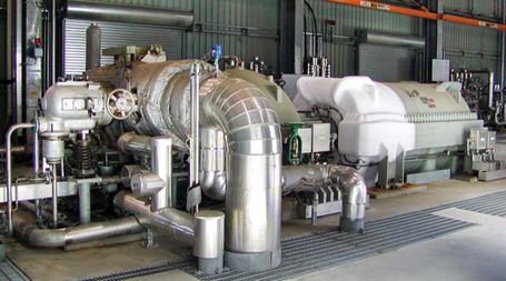
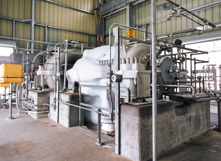
▲Figure 5. Centrifugal compressors in ethylene plants come in varying configurations and can handle large volumes. Photo courtesy of Elliot Group.
The names and process requirements of these compressors differ based on the process design (Figure 5).
Cracked-gas compressors
Also called process-gas or charged-gas compressors, cracked-gas compressors (CGCs) are high-power compressors that draw gas from the cracking furnaces through the various quench coolers and separation sections of the plant, and pressurize the gas for further separation. They are characterized by large volumes, high mass flowrates, low pressures, and the need for multiple compressor sections to meet the required discharge pressure. They typically have three to five sections across two or three compressor bodies of varying configurations.
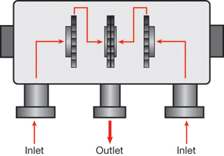
▲Figure 6. Double-flow compressors have two inlets with a common discharge.
The large volume requirement, and the need to reduce the head per stage due to fouling, make a double-flow configuration suitable for the first process stage of a cracked-gas compressor (Figure 6). A double-flow compressor is basically two smaller compressors arranged back to back with a common discharge. This configuration enables a much higher volume flow within a smaller and less-expensive compressor.
Generally, the pressure rise across a double-flow compressor is close to 2:1. After the double-flow compressor, the stream entering the second process stage is very similar aerodynamically to the stream that enters the pair of double-flow sections. The volume of the combined flow exiting the double-flow compressor is about equal to that of the stream entering each half of the double-flow compressor (double the mass flowrate at twice the pressure means the volumetric flowrate is very similar). This works very well for speed-matching the first and second sections. Because the same turbine drives the compressors, they operate at the same speed.
Fouling in CGCs
CGCs are susceptible to fouling due to polymerization. The cracked gas contains trace amounts of compounds that can polymerize within the gas stream and stick to the flow path in the compressor. This fouling degrades the performance of the compressor, which reduces throughput or increases power consumption.
There are two ways to deal with fouling — reduce the temperature to reduce the formation of fouling, or reduce the impact of fouling after it has formed.
Reduce temperature. The formation of foulants increases as the gas stream temperature increases. To reduce the discharge temperature (and thus the formation of foulants), limit the amount of head per section.
The temperature can also be reduced by increasing the number of compressor stages and cooling the gas stream with water injection after each compressor stage. However, increasing the number of compressor sections is very costly and has diminishing returns because interstage cooling temperatures are limited.
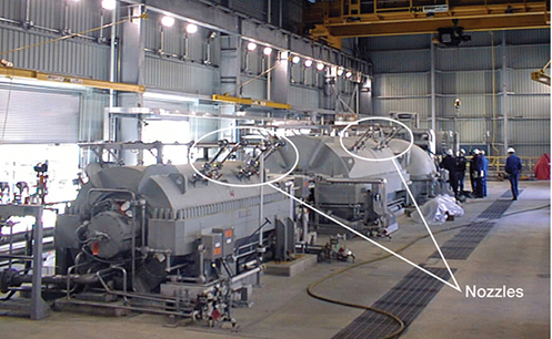
▲Figure 7. Nozzles are used to inject water into the gas stream within the compressor. Photo courtesy of Elliot Group.
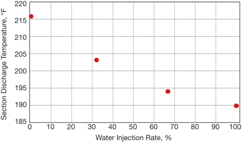
▲Figure 8. A 10–20°F reduction in temperature is typical with water injection cooling.
To reduce heat in the compressor, water injection is used to cool the gas stream within the compressor. Atomized water is injected into the gas stream through nozzles located in the return channel after each intermediate impeller (Figure 7). When the water contacts the hot gas, it flashes, removing heat from the gas stream, thereby allowing higher head without increasing the discharge temperature of the stream. The degree of cooling achieved varies, but a 10–20°F reduction is typical (Table 1 and Figure 8).
| Table 1. The amount of cooling that can be obtained by water injection is limited. | ||||
| Water Injection Rate | ||||
| 0% | 33% | 66% | 100% | |
| 1st Stage Discharge Temperature | 142°F | 142°F | 142°F | 142°F |
| Water Injection Flowrate, L/min | 27.8 | 55.6 | 84.2 | |
| 1st Stage Discharge Temperature After Water Injection | 136°F | 131°F | 128°F | |
| 2nd Stage Discharge Temperature | 179°F | 173°F | 168°F | 165°F |
| Water Injection Flowrate, L/min | 34.7 | 61.8 | 87.4 | |
| 2nd Stage Discharge Temperature After Water Injection | 166°F | 157°F | 152°F | |
| Section Discharge Temperature | 216°F | 203°F | 194°F | 190°F |
| Total Injection, L/min | 0 | 62.4 | 117.4 | 171.6 |
Reduce the impact of fouling. Reducing the impact of fouling can be achieved in two ways — preventing fouling from sticking to the flow path, or washing away any foulant that does stick to the flow path.
▲Figure 9. PTFE coatings offer good corrosion resistance in many applications, but are not very durable. This coating is shown brand new (top) and after 18 months in service (bottom). Photos courtesy of Elliot Group.

▲Figure 10. Electroless nickel coatings are more durable than PTFE coatings, and can remain intact for many years. The coating shown here has been in operation for six years. Photo courtesy of Elliot Group.
Coating the rotor and diaphragms with very slick coatings creates a surface that foulants cannot adhere to. Two common types of coatings are polytetrafluoroethylene (PTFE) (Figure 9) and electroless nickel. Both types have excellent surface properties that enable them to resist the buildup of foulant, but electroless nickel has a much harder and more durable surface, which offers additional advantages where aggressive wash oil and water injections are utilized (Figure 10).
Once fouling has occurred and has collected within the flow path, wash oil is used to physically remove the foulant. This is done by injecting wash oil into the inlet piping and intermediate return channels of the compressor through nozzles similar to those used for cooling water. The wash oil both dissolves and erodes foulant from the compressor’s flow path. Aggressive use of wash oil can cause erosion of coatings and even compressor components, but in general it is very effective at reducing the impact of fouling.
Refrigeration services
Although the configuration and refrigerant composition differ from plant to plant, all ethylene plants have two levels of refrigeration:
- C3 refrigeration, which provides refrigeration duty around –40°F using propane or propylene (or a mixture of the two)
- C2 refrigeration, which provides refrigeration duty down to –150°F using ethylene as a refrigerant (some process designs use a mixed-gas refrigerant for this service).
▲Figure 11. In existing plants, refrigeration compressors are easy to find because they are covered in frost. Photo courtesy of Elliot Group.
Refrigeration compressors are multisectional machines with sideloads or extractions depending on the process design (Figure 11). Mismatches of the head required per section and large swings in flowrates (between design and off-design performance) may impact overall compressor efficiency.
Refrigeration compressors differ from other process compressors in that the head across the entire compressor remains nearly constant at all flowrates. The discharge pressure is set by the condensing temperature of the refrigerant regardless of flow; the inlet pressure is directly related to the required duty temperature of the evaporators. These properties play an important role in dealing with centrifugal compressors in refrigeration services in off-design cases.
As the duties change, the mass flowrate from the evaporator(s) into the compressor changes, and thus the operating point on the head vs. volumetric flowrate compressor curve also changes. The compressor designer makes design decisions to best meet the customer’s requirements. Early collaboration between compressor designer, end user, and process designer allows for a better understanding of the long-term operation of the equipment and the design goals.
Sometimes, compromises made to accommodate off-design applications may reduce efficiencies at the normal operating points. For example, increasing the turndown of a refrigeration compressor without a recycle stream may create a wider, flatter compressor curve. Often, these modifications will reduce the efficiency at the rated and higher flowrates. The overall power consumption of the plant during the compressor’s operating life is important. Discuss any off-design applications with the compressor engineer so they can guide you to a more optimal solution.
Collaboration between the process designer and the compressor designer (i.e., the original equipment manufacturer [OEM]) can help improve the way the required section flowrates and the interstage pressures interact. For example, if duty is reduced, the flow into the section decreases, moving the operating point up and to the left on the curve. The increased head in the first section translates into a higher flange pressure for the first sideload. If this sideload serves a process function, this increase in pressure increases the temperature of this stream, which may not be desirable. The increase in head will cause the control system to slow the compressor to keep suction pressure and head constant.
At certain operating points, variations in the shape of the curve for different compressor sections means that the flange pressures may exceed the allowable tolerance. The compressor engineer may then attempt to make design changes to meet the tolerance, which may reduce performance at more important operating points.
Conclusion
Ethylene producers of all sizes are under pressure to continue to increase capacity at both existing and future plants. There is room for improvements in reliability, plant efficiency, and capital costs. A close working relationship between the process designer, plant operator, and the OEM is key to achieving these improvements.
Readers interested in compressors and turbines can learn more by attending the sessions organized by the Ethylene Plant Rotating Equipment Subcommittee at the 29th Ethylene Producers’ Conference being held as part of the 2017 AIChE Spring Meeting in San Antonio, TX.
Literature Cited
- American Petroleum Institute, “Axial and Centrifugal Compressors and Expander-Compressors,” API 617, 8th Ed, API, Washington, DC (Sept. 2014).
1

Copyright Permissions
Would you like to reuse content from CEP Magazine? It’s easy to request permission to reuse content. Simply click here to connect instantly to licensing services, where you can choose from a list of options regarding how you would like to reuse the desired content and complete the transaction.