
This article is based on a presentation given at the Kister Distillation Symposium at the AIChE Spring 2017 meeting in San Antonio, TX.
Process engineers are responsible for inspecting distillation columns. Follow this guide to prepare for a column inspection during a turnaround.
Turnarounds are planned opportunities to clean, fix, and revamp process equipment. Depending on the process and equipment, turnarounds might take place as often as every six months or as infrequently as every five or six years. Column inspections during turnarounds might be conducted because something is not working quite right or to confirm that everything inside the equipment is where it should be and is working correctly. A turnaround is one of the few times that process engineers get to see the inside of equipment. This is a valuable opportunity for troubleshooting operational problems.
Part 1 of this article describes the role and responsibilities of process engineers for inspections of distillation columns during turnarounds. The article also provides practical advice to guide engineers preparing for their first column inspection.
Think safety first
Personal safety. Personnel and site safety are of the utmost importance and the first consideration in planning any inspection. Each site has its own safety requirements. The minimum may include a site-specific safety training program and/or an area-wide cooperative safety program. The Delaware Valley Petroleum Refiners Association, for example, requires all employees working in their facilities to have process safety management (PSM) certification.
Entering a confined space, such as a distillation column, requires further training that conveys the additional hazards and associated safety requirements. An air mover may be required for ventilation, but this can increase noise as well as block an escape path. A person known as a “hole watch” is standard. Everyone entering the confined space needs to maintain communication with the hole watch, but in a noisy petrochemical plant, verbal communication is limited, usually necessitating radio communication. Always test radio-to-radio communication prior to entering the confined space to ensure communication is established.
Knowing your own limits is an important component of safety, both for yourself and your team. Consider your comfort with heights, confined spaces, and darkness, as well as your flexibility and conditioning. The decision to proceed throughout the inspection depends on your personal safety evaluation. Evaluations of safety should be constant and ongoing, because conditions and your perception of those conditions may change. Consideration of your ego should also be part of your personal safety evaluation. This is not just an issue for novices. Experience can cause you to ignore personal flexibility, conditioning, and encumbrance issues, pushing you to climb into a tight space that could be dangerous.
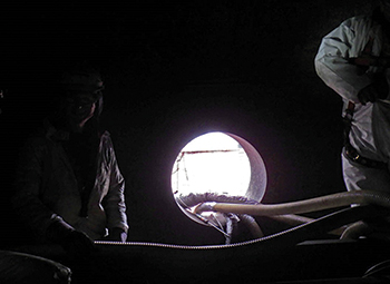
▲Figure 1. Hazards inside towers include darkness, hoses, and wires. Process inspections often take place during contractor breaks to minimize lost time.
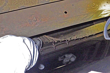
▲Figure 2. More than one worker or inspector in the same tower section make dropping equipment or dislodging a piece or part even more dangerous.
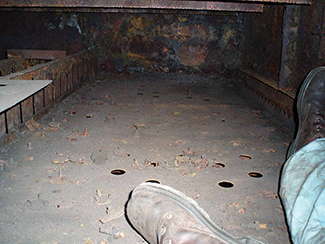
Safety hazards. Climbing outside and around equipment can be hazardous because of cluttered platforms and scaffolding close to ladders that may poke into the ladder cages. Darkness, cords, hoses, internal damage, and loose parts make climbing inside columns hazardous (Figure 1). Harnesses, coveralls, radios, and tools may encumber your movement when climbing and moving about small spaces. Falling objects like tray parts and tools can be a problem, especially when more than one person is in a tower at the same time in close proximity (Figure 2). Trays and other internals can be loose or corroded and may shift under weight. Sharp metal weirs, valves, bolts, and manways are everywhere in a tower, which make movement precarious.
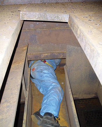
▲Figure 3. You need a plan for safely entering and exiting a tight space. Body harnesses and other equipment can restrict movement.
Tight spaces are a given in most towers (Figure 3). When space is extra tight, you need to evaluate how to get in and, more importantly, how to get out. Each entrance needs to have an exit plan for both normal circumstances and emergencies. For instance, are you starting at the top and going out of the bottom? Or, is there no bottom exit, and retracing your steps back up is the only way out? When transitioning past feed trays spaced five feet apart, do you know how to use the cross braces on the downcomers as a ladder to step down or back up? What are your options for getting out from the backside of a four-pass tray?
Dust and loose scale inside the column may require you to wear goggles or a mask. Old equipment may have asbestos gaskets, which require mitigation by an asbestos team. Iron sulfide may be present in any tower that has H2S or other sulfur contamination; amine units and some main fractionators can have significant deposits of iron sulfide. Most shutdown procedures include conversion of the iron sulfides to iron oxides, but complete conversion is not guaranteed. Iron sulfide in air converts to iron oxide under dry conditions at 104°F (40°C) and above — easily achieved near uninsulated tower walls on a hot summer day — and the byproducts of the reaction are sulfur acids that irritate the eyes and nose, can be dangerous to breathe, and can become pyrophoric.
Know the work plan and responsibilities
Plant management is primarily responsible for the turnaround and will delegate responsibilities to the turnaround project leader, who must complete the turnaround within the budget and schedule. The work plan should include a personnel chart with reporting relationships. Pre-turnaround meetings with representatives of project management, operations, and process engineering delineate responsibilities for specific activities. Each piece of equipment should be listed and its individual plan outlined, including cleanings and fixes of known problems. A sign-off chart for each step of the turnaround and each piece of equipment helps to ensure all turnaround activities are completed.
Operating personnel have the initial responsibility to shut down the operating units safely and perform activities necessary to enable blanking and other activities required for opening and entry. Once the turnaround begins, use morning and evening meetings at shift change to convey safety goals, reports, reminders, and statistics. Progress charts provide updates on the turnaround, including critical path tasks.
Process engineers’ responsibilities relate to many turnaround activities and parties involved. Maintenance, mechanical, and metal inspectors, as well as vendors and operators, may be present on-site. Metal inspectors evaluate vessel-wall integrity and attachment and tray problems related to metal thickness, as well as pitting and corrosion issues. Vendors may check to verify that the equipment has been installed in the right place, correctly, and with the correct hardware. Operators may take a final look to ensure that all trash and maintenance equipment has been removed before authorizing closure.
As a process engineer, you understand how the tower works and how the mechanical pieces and parts need to fit together. Your responsibility will likely be to provide inspection punch lists and work with mechanical inspectors to create change orders. Major changes that affect process operations should prompt a process-of-change meeting, attended by process engineers, mechanical engineers, and operations personnel. You should conduct follow-up inspections to ensure changes and fixes are correct, and you should be involved in the sign-off process to complete and approve column closure.
Come prepared
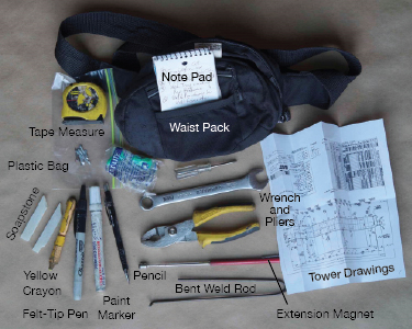
▲Figure 4. I keep this equipment in my waist pack for standard inspections.
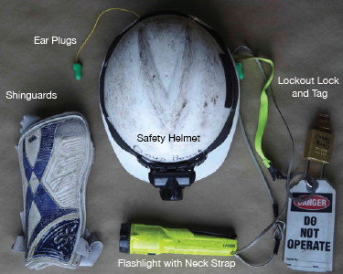
▲Figure 5. I wear this safety equipment and bring my lockout lock and tag with me to all inspections.
Throughout the years, the equipment I use for inspections has changed and improved. I carry some items for safety reasons and others because I anticipate I may need them. These are my personal suggestions for equipment and tools that I carry with me in a pocket or waist pack (Figures 4 and 5). (Distributor test equipment and water tightness test equipment is covered in Part 2 of this article.)
Lockout lock and tag. For safety, most plants require some form of lockout/tagout. It is your safety that is at risk, so you have the right to verify isolation blanks and isolation of power, energy, liquid, and gas sources. Placing your lock at the appropriate location signifies your presence in the unit and acknowledges that you believe the process and power to the tower is isolated.
Extending magnet and bent weld rod. A magnet on an extendable rod is useful for preliminary checks of metallurgy and collecting stray pieces of carbon steel or Type 410 stainless steel hardware. A bent piece of 1/8-in. weld rod can be used to probe corrosion patches and estimate the size of cracks and holes.
Plastic storage bags. Keep these on hand to collect corrosion samples or strange pieces of hardware, etc.
Note pad and digital camera. I highly recommend bringing a note pad. Digital cameras are also an excellent way to document problems you encounter. Remember that most cameras require a hot work permit.
Detailed tower and tray/internals drawings and punch list. Drawings are useful for comparing what you see with the intended design. You should bring a tower drawing that includes tray/packing, external manway, and feed/draw locations.
There are multiple ways to keep track of inspection issues that need to be corrected. A punch list with notes is common. For an inspection of a new tower with many trays, carry a photocopy of each tray (multiple trays per sheet) and mark on the mini-drawings the location of any loose or missing hardware. Contractors can then use these drawings to guide their work and you can use them to conduct a follow-up inspection.
Various markers, pens, and pencils. You may need to make marks and indications on trays and walls. Soapstone, crayon, black marker, and chloride-free paint pen mark on everything from rusty iron to shiny new stainless steel. You will undoubtedly drop your pen or pencil or run out of lead or ink, so keep several on hand.
Tape measure and small metal rule. Depending on the vessel size, a 10–25-ft tape measure should be sufficient to verify dimensions. A 6-in. metal rule can be useful for checking downcomer escape and weir heights.
Wrench and pliers. A 9/16-in. wrench will fit most tray hardware and pliers will work for most other sizes, as well as serve as a second wrench if needed to loosen or check the tightness of a part. A short arm torque wrench is another useful tool.
Light sources. Contractor lights in towers are unreliable — they go out unexpectedly and are not always in the right spot. Always have two light sources of your own. A helmet light is a good primary light. After having my helmet light knocked off, I added Velcro fastening to the front and sides of the strap. I also carry a separate flashlight around my neck, which is good for any directional light need and for shining downward (hands free) while descending through internal manways. Hanging the light around your neck also eliminates the potential for dropping it. Know how many hours of light each of your light sources can provide. Remember that battery performance decreases with temperature. Fresh batteries are cheap insurance against getting stuck in the dark.
Goggles, dust mask, or face mask. Ensure any mask you are required or advised to wear is treated with anti-fog coating and tested. Goggles that are fogged can be more dangerous than no goggles at all. Make sure that any cartridge mask has the proper cartridge for the service.
Shinguards and/or kneepads. After decades of banging my shins against metal, my grandkid’s soccer match gave me the idea to add shinguards to my inspection kit. It was definitely a moment that made me ask, “Why didn’t I think of that sooner!”
Dimension and tolerance table. A table of critical dimensions can be useful, especially for multiple checks of new tray installations. A weir/downcomer dimension template can then be used to quickly check several places across the downcomer escape or weir to verify that the dimensions are within tolerance. The template should be cut to represent design minimum and maximum acceptable dimensions. A stiff plastic that can be cut with scissors is the best material.
Level devices. Occasionally trays and packing distributors need to be checked for levelness. Bubble levels, water levels, or laser levels all may be appropriate, depending on the accuracy required and the physical arrangement being checked. Whatever device you use, test its accuracy. To check bubble levels and water levels, simply reverse the device to assure that the reading is the same in both directions. Laser devices need to be self-leveling or they are no better than a bubble level.
Mirror on a stick. A mirror attached to a stick lets you see around corners and places where your head does not fit.
Lay the foundation for process inspections
You need to be able to answer the following questions before starting an inspection.
How do the parts fit together? The mechanical engineer or specialist you are working with can help you understand how the parts of the tower fit together. You need to know this information as a basis for determining whether the tower is physically and mechanically as intended.
How does the process work? As a process engineer, understanding the process is your job. Knowing the process inside and out can help prevent incorrect installations that may meet the mechanical design but not the process design.
How do the parts work together? If you know how each part of the column works with the other parts, you can look for parts that are not operating correctly. It is important to understand the interactions of the open area on a tray, the downcomer entrance area, escape area and weir height, and the tray-to-tray dimensions as they relate to the process vapor and liquid flowrates.
How do deviations affect the process? For instance, the downcomer clearance in a high-pressure, high-capacity propylene splitter may be critical to the downcomer backup design. The downcomer clearance may be much less critical in a low-pressure main fractionator. A critical dimension may limit the capacity of a tower, and a high pressure drop may limit capacity or increase energy consumption.
When is the next turnaround scheduled? Consider that the next chance to fix a problem may be five years away. Turnarounds are always limited by cost and time, and fixes take time and money. You must understand the economic impacts of issues uncovered during inspection, and be prepared to make a case to management for accepting the cost and/or schedule penalties incurred by making a change.
Conduct a turnaround tray inspection
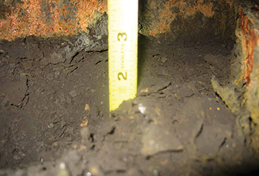
▲Figure 6. Deposits accumulate on tray decks, especially under downcomers and in seal and draw pans. These deposits accumulate during process operations and/or are flushed from other surfaces during shutdown washes.
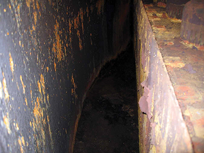
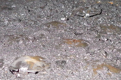
▲Figure 7. Loose scale should be scraped or brushed off all surfaces to prevent flaking off into the process.
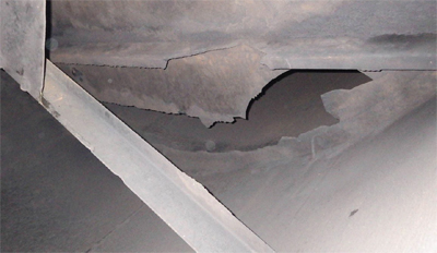
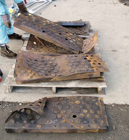
▲Figure 8. You will need to decide whether cracked trays can be repaired or must be replaced.
Take these steps to ensure a successful and comprehensive inspection.
- Number the trays for reference. Make sure you number the trays starting at the top or bottom according to the column drawings. Ensure any inspection notes or punch list items include a location reference based on this numbering.
- Note cleaning issues. Take photos to describe and define visually any cleaning problems you find (Figures 6 and 7). Some towers contain such extensive deposits that even a preliminary mechanical/process inspection cannot be completed without some initial cleaning. The nature of the cleaning issues (loose deposits or hard scale) helps to inform the type and extent of cleaning required. Loose deposits can be vacuumed, while friable deposits can be scraped, brushed, and vacuumed. Hard scale may have to be chipped by a nail gun before it can be vacuumed. You may have to make a pragmatic decision on what is functionally clean and acceptable.
It is critical that cleaning is done on some key areas. Deposits under downcomers, in seal and draw pans, and on or under valves can constrain capacity. Loose or potentially loose deposits on walls, downcomer panels, and tray decks may not immediately limit function or capacity, but loose deposits often migrate and foul reboilers and other exchangers. - Note damage and missing or loose items. Take note of any missing or stuck valves and loose or missing hardware. Missing and stuck valves may often be observed visually, but stuck valves may require hands-on verification. Make sure to note any loose or missing hardware, which may indicate past operating problems. Survey trays for cracks, damage, and/or corrosion (Figure 8), and determine whether the damage is repairable or requires replacement. Also, make a note of the condition of internal manway hardware. Review the condition of all auxiliary internals, including feed pipes, vortex breakers, and nozzles of various instruments.
- Prepare a punch list and your recommendations. You will need this list to guide further inspections and turnaround activities.
Look for these common problems
▲Figure 9. Examine loose valves and the empty holes to determine what displaced the valves.
Displaced, stuck, or plugged valves. If a tower has moving valves, you will likely find a few, or many, displaced and missing (Figure 9). Before considering a replacement strategy, investigate the cause.
If the valves are missing, examine some of the loose valves for clues. Are the legs worn off or thin, indicating wear from erosion-corrosion? Are the valves and legs perfect and fit easily back into the hole, indicating improper installation? Check the valve hole condition for erosion-corrosion, which can increase the hole diameter and/or thin the tray deck. Check the rest of the tray for evidence of a process upset that may have disturbed the valves. The tray may have thinned due to corrosion or cracked around the missing valves.
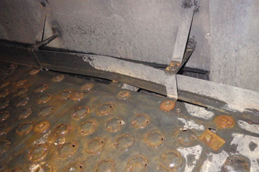
▲Figure 10. Deposits above and below decks need to be removed to enable full movement of valves.
Moving valves must have full travel, which may require removal of deposits around the caps of valves that are stuck or plugged with deposits, including the legs below the tray deck (Figure 10). Deposits on and under the decks need to be removed to assure movement and full vapor capacity. A typical acceptable exception is 1% nonfunctional valves or holes.
Replacement of worn or missing valves must be done correctly. The valve legs must be bent to prevent the valve from falling out of the hole, but the valve must also be free to move up and down. Discuss installation techniques with the contractor and conduct a follow-up check — otherwise they will likely only drop the valve into the hole and it will pop out as soon as vapor is introduced. Valves with cages must have the cage leg tabs bent away from the center to properly secure the cage to the deck.
Moving valves sometimes have oversized holes due to erosion-corrosion. A temporary fix — instead of replacing the whole tray deck — might include adding light-gauge retainer rings that sit on the valve feet below the tray deck. These rings both retain the valves and simulate the original valve opening when in the open position.
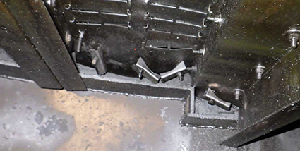
▲Figure 11. Manway clips with a permanent bend must be replaced, preferably with 3/16-in.-thick clips.
Manway problems. Every shutdown or turnaround inspection of internal trays includes opening the internal manways. Many boilermakers use the quickest method of removal, which is to hammer the manway clips to the open position. This leaves the hardware frozen in the closed position. In addition, the original tray clips are typically of a light gauge that easily bends when overtightened or subjected to a process upset. Any clips that are permanently bent (Figure 11) must be replaced, preferably with a 3/16-in.-thick clip. Have someone loosen each manway nut and bolt and replace any seized hardware. You may have to take responsibility for this task to ensure it is completed.
Check that all corrections have been made before authorizing closure of internal manways. Failure to loosen and/or replace manway hardware can cause delays in the closure process or skipped closure due to time, pressure, and human nature. Improper closure has consequences, including a column that is less resistant to upsets and stainless steel decks that are susceptible to vibration-induced cracking. Poor closure ultimately can cause tray failures and operating limitations.
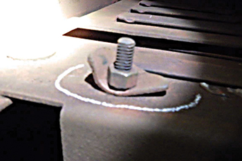
Many older installations of Nutter valve trays have unique manway hardware. The manway closure is composed of sliding clips and rectangular washers. Clips can be installed in four different ways, but only one way is correct. If you know you are dealing with Nutter trays, request a copy of the clip orientation drawing and discuss it with the installers of the replacement hardware. Nutter trays have rectangular slots and square bolts. Hammering the hardware open to release the internal manways can damage the bolts and/or the rectangular slots.
▲Figure 12. Nutter-style internal sliding manway clips have only one correct installation orientation.
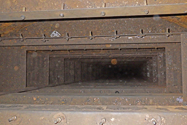
▲Figure 13. Blind fastening of internal manways is difficult because the clips are not visible to the installer while they are being tightened.
Blind fastening, in which the securing clip of the manway is not visible to the installer because the clip is on the blind side of the installed tray manway, makes tray installation difficult (Figures 12 and 13). Most of these trays have one of two basic types of hardware — Nutter sliding clips or football-type clips (i.e., rotating half-moon clips) — that require different techniques.
Installers of the sliding clips must orient all bolts/clips to the open position before setting the manway. Then, they must slide each clip into the closed position and maintain the bolt’s orientation while tightening the nut.
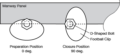
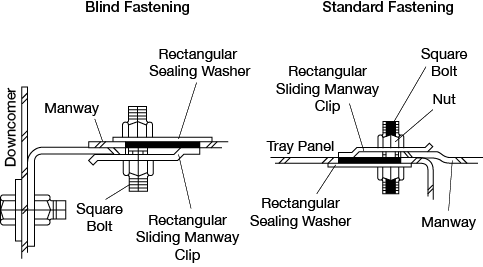
▲Figure 14. This diagram of a manway panel shows one blind clip in position for installation and a second clip turned 90 deg. to the closed position.
Installers of football-type clips must orient the footballs at 90 deg. to the closure position. After the manway is set in place, they must rotate each bolt 90 deg., which turns the clip to the closed position. The bolt’s orientation must be held while the nut is tightened. The bolt is shaped like a D and the clip has a matching D-shaped hole so that the bolt and clip can be turned together with positive positioning (Figure 14).
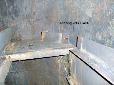
▲Figure 15. This weir has been displaced and pushed away from under its retaining washers. Tower liquid can then bypass the weir through the gap under the weir.
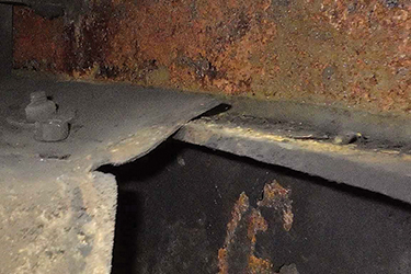
▲Figure 16. This downcomer clip is bent from overtightening and has come loose, reducing the integrity of the attachment.
▲Figure 17. A misoriented ring clip does not help hold the tray deck in place.
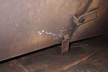
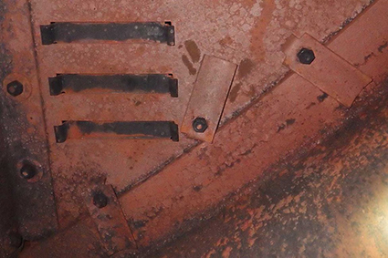
▲Figure 18. The opening indicates the location of a missing piece of swept-back weir, which allows liquid to bypass the weir, causing maldistribution of liquid on the operating tray. The most probable causes for the missing piece are poor tightening of the bolting hardware or loosening of the hardware by vibration.
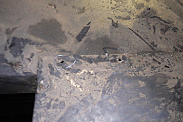
▲Figure 19. Missing bolting hardware reduces the mechanical integrity of the tray, and is typically caused by vibration and/or loose installation.
Miscellaneous hardware issues. In addition to valve and manway problems, look for displaced weirs (Figure 15), bent and/or loose downcomer clips (Figure 16), ring clips that are askew (Figure 17), missing weir pieces (Figure 18), and missing deck bolts (Figure 19).
Analyze tray damage
Most turnaround teams must deal with at least one tower with expected or unexpected damage. The damage may be expected due to process rate limitations or separation quality issues, and a gamma scan may have already indicated a probable tray upset or other issue. You will need to analyze the damage and give a reasonable description of the probable cause, as well as determine the parts that need to be ordered. Look for the following four major types of tray damage.
▲Figure 20. Over tightening of ring clips can bend the perimeter edge of the tray deck.
Trays that are bent or cracked. Trays may bend over the years from the weight of heavy boilermakers and inspectors climbing on them. Bending usually occurs at the weakest point of the tray deck — the edge of the tray next to the internal manway at the support ring. Overtightening of the ring clips can also bend the tray deck down at the edge near the support ring (Figure 20).
▲Figure 21. Water hammer through high levels of liquid can push trays up.
▲Figure 22. A water explosion lifted this tray from its supports.
Trays that are pushed up. Level losses and internal water explosions can bend trays and/or loosen attachment hardware. Out-of-control high levels into trays in the bottom of a tower causes vapor to percolate through the liquid, creating a water hammer effect that can push trays up (Figure 21). Low-pressure and vacuum towers are susceptible to water explosions because water entering a hot tower can instantly vaporize. These explosions initially push and deform trays upward (Figure 22).
Trays that are pushed down. Trays that have been pushed down often look like Bigfoot has stepped on them. The main cause is loss of liquid level control in the bottom of a column. This type of damage occurs most often with moving-valve trays, in which operators compensate for high liquid level by pulling liquid out of the bottom of the tower as fast as possible to correct the problem. The moving valves act like check valves and force all the extra liquid down the downcomers. The sudden liquid movement creates a vacuum below the trays, pulling them down. Water explosions introduced from a feed, recycle, or pump-around return above the affected trays may also push them down. Breaking vacuum too quickly can cause this type of damage, as well.
Trays that are pushed up and down. A water explosion at an intermediate location in the tower may push trays up above the explosion and push them down below the explosion. The extent of the damage may decrease as the distance from the source increases — as the pressure pulse expands, the effect decreases.
Learn these lessons
Secure small parts. A tower had serious erosion--corrosion issues, requiring new valves and retaining rings. The rings were received at the site but, when it was time for the installation, the rings could not be found. The rings had to be reordered, which delayed tower startup. Keep a paper trail of all critical nonstock small parts, including who received the items and any subsequent passing of responsibility.
Spray nozzles are unique items that are supplied by vendors that typically supply carwashes and firewater systems. Refineries and chemical plants must special-order spray nozzles with a specific metallurgy and design. Expedited manufacture and delivery can take seven to ten days.
For inspection, spray nozzles must be removed and checked from the inlet side and cleaning or replacement may be required. A plant sent nozzles for cleaning and, when it came time to reinstall the nozzles, they could not be found. To prevent a costly startup delay, the plant was able to find similar nozzles at another refinery, but accommodating the different nozzles required a quick redesign of the piping manifold. Small critical parts need to be tracked and secured at every step of the process — from removal, to cleaning and storage, to reinstallation.
Conduct process revamp reviews and field dimension checks. A stripping tower had flooding issues. Without a process engineering review, the maintenance department installed block valves on a side reboiler that was causing maintenance problems. The intent was to allow the reboiler to be taken offline during operation. However, the reboiler draw tray had no internal downcomer and, therefore, could not be blocked off and isolated. In addition, the block valves caused additional pressure drop in the reboiler circuit and initiated a flood.
Had the change undergone a process review, the block valves would never have been installed. A gamma scan confirmed flood initiation above the reboiler draw and also showed a second flood initiation several trays above. The second flood was not anticipated based on the loading simulation. When the tower was shut down to remove the extraneous reboiler block valves, a dimension check showed the downcomer inlet dimension at the flood point was 3/4 in. narrower than intended. The downcomer inlet area was the process-limiting factor, and adjustment of the downcomer inlet increased capacity by 5%.
A foul-water stripper experienced an upset and several trays needed to be repaired and replaced. The drawings indicated 1/4-in. stainless steel tray support rings, but 3/4-in. carbon steel rings had been installed without an update to the drawings. Because a field check had been conducted, the correct size of support ring clamps were ordered, preventing a startup delay.
Remember your role as a process engineer
The process engineer is in a unique position. We have little authority. We don’t control a budget, and we can’t order a change in operations or maintenance procedures. But, we have much responsibility. We can see the theoretical and practical reasons for making a change to improve operation and maintenance, and we need to make improvements happen, which requires us to sell our solutions.
We are a bridge between operations, maintenance, and management. We have to rise above plant politics and drive economic optimization. We need to recognize that relationships create influence, influence creates accepted recommendations, accepted recommendations create improvements, improvements create more profits, and more profits create stable companies and jobs.
Part 2 of this article will cover additional revamp field inspection examples, special inspections, and specific inspections for structured and random packed systems.
Additional Resources
Bouck, D., “Ten Distillation Pitfalls to Avoid,” Chemical Engineering Progress,110 (2), pp. 31–38 (Feb. 2014).
Olsen, T., “Turnarounds: Strategic Opportunities to Improve,” Chemical Engineering Progress,114 (8), pp. 46–50 (Aug. 2018).
1

Copyright Permissions
Would you like to reuse content from CEP Magazine? It’s easy to request permission to reuse content. Simply click here to connect instantly to licensing services, where you can choose from a list of options regarding how you would like to reuse the desired content and complete the transaction.