
Ammonia is critical in the manufacturing of fertilizers, and is one of the largest-volume synthetic chemicals produced in the world. This article explores the evolution of ammonia production and describes the current manufacturing technologies.
Most people associate the pungent smell of ammonia (NH3) with cleaners or smelling salts. However, the use of ammonia in these two products represents only a small fraction of the total global ammonia production, which was around 176 million metric tons in 2014 (1). To appreciate where the industry and technology are today, let’s first take a look at how we got here.
Ammonia has been known for more than 200 years. Joseph Priestley, an English chemist, first isolated gaseous ammonia in 1774. Its composition was ascertained by French chemist Claude Louis Berthollet in 1785. In 1898, Adolph Frank and Nikodem Caro found that N2 could be fixed by calcium carbide to form calcium cyanamide, which could then be hydrolyzed with water to form ammonia (2):
CaO + 3C ↔ CaC2 + CO
CaC2 + N2 ↔ CaCN2 + C
CaCN2 + 3H2O ↔ CaCO3 + 2NH3
The production of significant quantities of ammonia using the cyanamide process did not occur until the early 20th century. Because this process required large amounts of energy, scientists focused their efforts on reducing energy requirements.
German chemist Fritz Haber performed some of the most important work in the development of the modern ammonia industry. Working with a student at the Univ. of Karlsruhe, he synthesized ammonia in the laboratory from N2 and H2.
Meanwhile, Walther Nernst, a professor of physical chemistry at the Univ. of Berlin, developed a process to make ammonia by passing a mixture of N2 and H2 across an iron catalyst at 1,000°C and 75 barg pressure. He was able to produce larger quantities of ammonia at this pressure than earlier experiments by Haber and others at atmospheric pressure. However, Nernst concluded that the process was not feasible because it was difficult or almost impossible (at that time) to produce large equipment capable of operating at that pressure.
Nonetheless, both Haber and Nernst pursued the high-pressure route to produce ammonia over a catalyst. Haber finally developed a process for producing commercial quantities of ammonia, and in 1906 he was able to achieve a 6% ammonia concentration in a reactor loaded with an osmium catalyst. This is generally recognized as the turning point in the development of a practical process for the production of ammonia in commercial quantities.
Haber realized that the amount of ammonia formed in a single pass through a converter was far too low to be of commercial interest. To produce more ammonia from the makeup gas, he proposed a recycle system, and received a patent for the concept. Haber’s recycle idea changed the perception of process engineering as static in favor of a more dynamic approach. In addition to the chemical reaction equilibrium, Haber recognized that reaction rate was a determining factor. Instead of simple yield in a once-through process, he concentrated on space-time yield in a system with recycle.
BASF purchased Haber’s patents and started development of a commercial process. After testing more than 2,500 different catalysts, Carl Bosch, Alvin Mittasch, and other BASF chemists developed a promoted iron catalyst for the production of ammonia in 1910. Developing equipment that could withstand the necessary high temperatures and pressure was an even more difficult task. An early mild steel reactor lasted only 80 hours before failure due to decarbonization. Lining mild steel reactors with soft iron (which was not vulnerable to decarbonization) and adding grooves between the two liners to release hydrogen that had diffused through the soft iron liner solved this problem. Other major challenges included designing a heat exchanger to bring the inlet gas to reaction temperatures and cool the exit gas, and devising a method to bring the catalyst to reaction temperature.
The first commercial ammonia plant based on the Haber-Bosch process was built by BASF at Oppau, Germany. The plant went on-stream on Sept. 9, 1913, with a production capacity of 30 m.t./day.
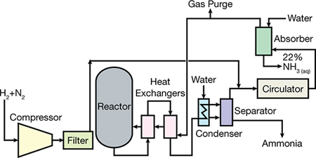
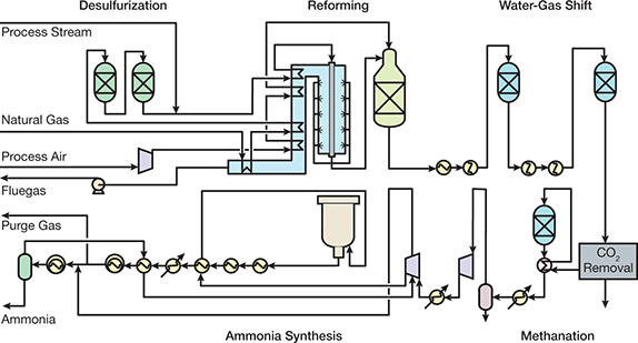
▲Figure 1. This is a simplified flowsheet of the first commercial ammonia plant by BASF.
Figure 1 is a flowsheet of the first commercial ammonia plant. The reactor contained an internal heat exchanger in addition to those shown on the schematic.
Global production rates
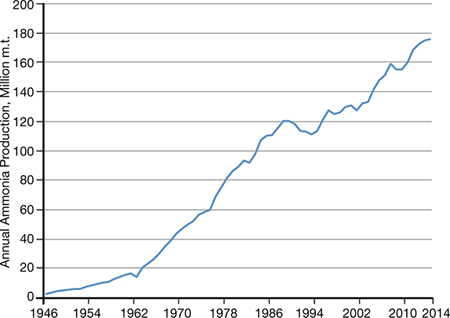
▲Figure 2. Worldwide ammonia production has steadily increased from 1946 to 2014.
Ammonia production has become one of the most important industries in the world. Without the crop yield made possible by ammonia-based fertilizers and chemicals, the global population would be at least two to three billion less than it is today (3). Ammonia production has increased steadily since 1946 (Figure 2), and it is estimated that the annual production of ammonia is worth more than $100 billion, with some plants producing more than 3,000 m.t./day of NH3.
In 1983, on the occasion of the 75th anniversary of AIChE’s founding, a blue ribbon panel of distinguished chemical engineers named what they believed to be the world’s ten greatest chemical engineering achievements (4). Embracing such feats as wonder drugs, synthetic fibers, and atomic energy, the citation also included the breakthrough that permitted the production of large quantities of ammonia in compact, single-unit plants.
Within the past decades, chemical engineers have succeeded in creating processes that make vast amounts of ammonia at relatively low costs. As recently as 80 years ago, the total annual production of synthesized ammonia was just over 300,000 m.t. Thanks to chemical engineering breakthroughs, one modern ammonia plant can produce more than 750,000 m.t./yr.
Approximately 88% of ammonia made annually is consumed in the manufacturing of fertilizer. Most of the remainder goes into the production of formaldehyde. China produced about 32.6% of the global production in 2014, while Russia, India, and the U.S. produced 8.1%, 7.6%, and 6.4%, respectively (1). While most of the global production of ammonia is based on steam reforming of natural gas, significant quantities are produced by coal gasification; most of the gasification plants are located in China.
Modern production processes
The tremendous increase in ammonia demand from 1950 to 1980 necessitated larger, more-energy-efficient plants. Those decades also saw a change in design philosophy. Until that time, an ammonia plant was regarded as an assembly of unrelated units, such as gas preparation, gas purification, gas compression, and ammonia synthesis. New innovations and an integral design tied process units together in the most effective and efficient ways.
▲Figure 3. KBR designed one of the first single-train, large-capacity ammonia plants.
In the mid-1960s, the American Oil Co. installed a single-converter ammonia plant engineered by M.W. Kellogg (MWK) at Texas City, TX, with a capacity of 544 m.t./day. The single-train design concept (Figure 3) was so revolutionary that it received the Kirkpatrick Chemical Engineering Achievement Award in 1967.
The plant used a four-case centrifugal compressor to compress the syngas to a pressure of 152 bar, and final compression to an operating pressure of 324 bar occurred in a reciprocating compressor. Centrifugal compressors for the synthesis loop and refrigeration services were also implemented, which provided significant cost savings.
The key differences between the MWK process and the processes used in previous ammonia plants included:
- using a centrifugal compressor as part of the synthesis gas compression
- maximizing the recovery of waste heat from the process
- generating steam from the waste heat for use in steam turbine drivers
- using the refrigeration compressor for rundown and atmospheric refrigeration.
An integrated scheme that balanced energy consumption, energy production, equipment size, and catalyst volumes was incorporated throughout the plant.
Most plants built between 1963 and 1993 had large single-train designs with synthesis gas production at 25–35 bar and ammonia synthesis at 150–200 bar. Another variation by Braun (now KBR) offered slight modifications to the basic design. The Braun Purifier process plants utilized a primary or tubular reformer with a low outlet temperature and high methane leakage to reduce the size and cost of the reformer. Excess air was added to the secondary reformer to reduce the methane content of the primary reformer exit stream to 1–2%. Excess nitrogen and other impurities were removed downstream of the methanator. Because the synthesis gas was essentially free of impurities, two axial-flow ammonia converters were used to achieve a high ammonia conversion.
Some recently built plants have a synthesis gas generation system with only one reformer (no secondary reformer), a pressure-swing adsorption (PSA) system for H2 recovery, and an air separation plant as the source of N2. Improvements in converter design, such as radial and horizontal catalyst beds, internal heat exchangers, and synthesis gas treatment, helped increase ammonia concentrations exiting the synthesis converter from about 12% to 19–21%. A higher conversion per pass, along with more-efficient turbines and compressors, further reduced energy consumption. More-efficient CO2 removal solutions, such as potassium carbonate and methyldiethanolamine (MDEA), have contributed to improved energy efficiency. Most modern plants can produce ammonia with an energy consumption of 28 GJ/m.t.
In addition to the design, mechanical, and metallurgical improvements made during this time, the operating pressure of the synthesis loop was significantly reduced. When the first single-train plant was built in the 1960s, it contained a high-pressure synthesis loop. In 1962, MWK received an inquiry from Imperial Chemical Industries (ICI) for a proposal to build a 544-m.t./day plant at their Severnside site. MWK proposed a 152-bar synthesis loop instead of a 324-bar loop.
Because the development of kinetic data for the ammonia reaction at 152 bar would take more time than MWK had to respond to the ICI inquiry, they contacted Haldor Topsøe to support their plans. Topsøe had data covering the entire pressure range of interest to MWK. In addition, they had a computer program for calculating the quantity of catalyst that was required at the lower operating pressure. Even though ICI chose Bechtel to design the plant, MWK was able to develop a flowsheet for a 544-m.t./day design with centrifugal compressors and a low-pressure synthesis loop, which some people consider the single most important event in the development of the single-train ammonia plant.
Approximately twice as much catalyst was required at 152 bar as at 324 bar, an increase that seemed economically feasible. Although the converter would need twice the volume, the lower operating pressure would reduce the required thickness of the pressure shell. As a result, the weight of metal required for the converter plus the catalyst remained about the same. The lower-pressure synthesis loop also allowed the use of centrifugal compressors instead of reciprocating compressors. Another improvement was recovering heat to generate high-pressure steam for steam turbine drives.
Plant designs in the 21st century
During the first few years of the 21st century, many improvements were made in ammonia plant technology that allow existing plants to increase production rates and new plants to be built with larger and larger capacities. Competition between technology suppliers is quite fierce. Three technology licensors — KBR (Kellogg Brown and Root), Haldor Topsøe, and ThyssenKrupp Industrial Solutions (TKIS) — currently dominate the market. Ammonia Casale, which offers an axial-radial catalyst bed design, is a market leader in revamps of existing plants.
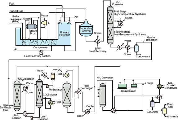
▲Figure 4. Modern ammonia plants designed by KBR employ its proprietary Purifier design.
Most of the ammonia plants recently designed by KBR utilize its Purifier process (Figure 4), which combines low-severity reforming in the primary reformer, a liquid N2 wash purifier downstream of the methanator to remove impurities and adjust the H2:N2 ratio, a proprietary waste-heat boiler design, a unitized chiller, and a horizontal ammonia synthesis converter.
Depending on the configuration of the plant, energy consumption can be as low as 28 GJ/m.t. Because the secondary reformer uses excess air, the primary reformer can be smaller than in conventional designs. The cryogenic purifier (shown in Figure 4 in light green with a light orange background), which consists of an expander, condenser, feed/effluent exchanger, and rectifier column, removes impurities such as CO, CH4, and argon from the synthesis gas while adjusting the H2:N2 ratio of the makeup gas in the ammonia loop to the optimum level. The ammonia concentration exiting the low-pressure-drop horizontal converter is 20–21%, which reduces energy requirements for the recycle compressor. KBR also offers a low-pressure ammonia loop that employs a combination of magnetite catalyst and its proprietary ruthenium catalyst.
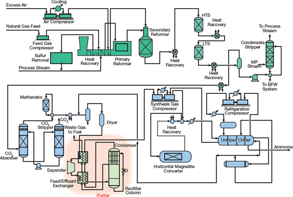
▲Figure 5. Haldor Topsøe offers an ammonia plant design that has a proprietary side-fired reformer in which radiant burners supply heat for the reforming reaction.
The syngas generation section (or front end) of a Haldor Topsøe-designed plant (Figure 5) is quite traditional with the exception of its proprietary side-fired reformer, which uses radiant burners to supply heat for the reforming reaction. Haldor Topsøe also offers a proprietary iron-based synthesis catalyst, radial-flow converters consisting of one, two, or three beds, and a proprietary bayonet-tube waste-heat boiler. More recent developments include the S-300 and S-350 converter designs. The S-300 converter is a three-bed radial-flow configuration with internal heat exchangers, while the S-350 design combines an S-300 converter with an S-50 single-bed design with waste-heat recovery between converters to maximize ammonia conversion.
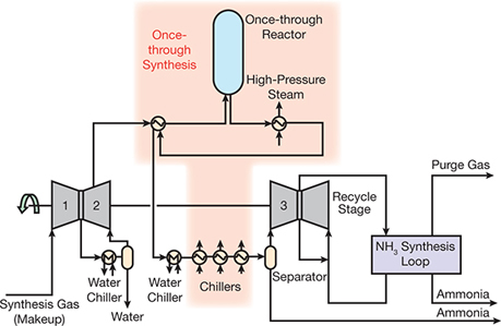
▲Figure 6. ThyssenKrupp’s dual-pressure synthesis loop design features a once-through reactor between syngas compressors.
ThyssenKrupp offers a conventional plant (Figure 6) with a unique secondary reformer design, a proprietary waste-heat boiler, radial-flow converters, and a dual-pressure ammonia synthesis loop. Today, a production rate of 3,300 m.t./day can be achieved using the TKIS dual-pressure process.
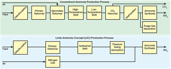
▲Figure 7. The Linde Ammonia Concept (LAC) features a pressure-swing adsorption unit for high-purity hydrogen production and an air separation unit for high-purity nitrogen production.
The Linde Ammonia Concept (LAC) is an established technology process scheme with over 25 years of operating experience in plants with capacities from 200 m.t./day to over 1,750 m.t./day. The LAC process scheme (Figure 7) replaces the costly and complex front end of a conventional ammonia plant with two well-proven, reliable process units:
- production of ultra-high-purity hydrogen from a steam-methane reformer with PSA purification
- production of ultra-high-purity nitrogen by a cryogenic nitrogen generation unit, also known as an air separation unit (ASU).
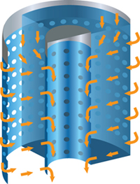
▲Figure 8. Ammonia Casale’s process employs a catalyst bed that harnesses axial-radial technology, which has a lower pressure drop and higher efficiency than standard catalyst beds.
Ammonia Casale’s plant design has a production rate of 2,000 m.t./day. One of the key features of this design is axial-radial technology in the catalyst bed (Figure 8). In an axial-radial catalyst bed, most of the synthesis gas passes through the catalyst bed in a radial direction, creating a very low pressure drop. The rest of the gas passes down through a top layer of catalyst in an axial direction, eliminating the need for a top cover on the catalyst bed. Casale’s axial-radial catalyst bed technology is used in both high-temperature and low-temperature shift converters, as well as in the synthesis converter.
Other technologies
Some technology suppliers have offered gas-heated reformers (GHRs) for the production of ammonia in small-capacity plants or for capacity increases. Unlike conventionally designed plants that use a primary reformer and secondary reformer operating in series, plants with GHRs use the hot process gas from the secondary reformer to supply heat to the primary reformer. This reduces the size of the primary reformer and eliminates CO2 emissions from the primary reformer stack, making the process more environmentally friendly.
Even though some ammonia producers advocate for distributed production of ammonia in small ammonia plants, most companies prefer to build large facilities near cheap raw material sources and transport the product by ship, rail, or pipeline to the consumers.
Ammonia from coal
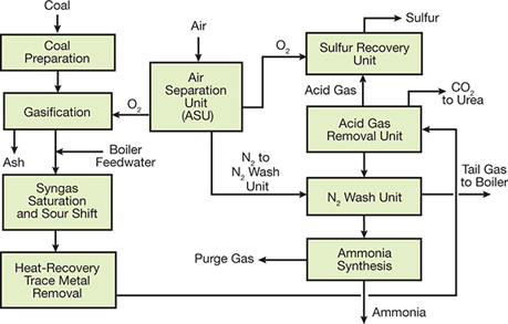
▲Figure 9. China produces most of its ammonia from coal.
China produces more ammonia than any other country, and produces the majority of its ammonia from coal (Figure 9).
The basic processing units in a coal-based ammonia plant are the ASU for the separation of O2 and N2 from air, the gasifier, the sour gas shift (SGS) unit, the acid gas removal unit (AGRU), and the ammonia synthesis unit. Oxygen from the ASU is fed to the gasifier to convert coal into synthesis gas (H2, CO, CO2) and CH4. There are many gasifier designs, but most modern gasifiers are based on fluidized beds that operate above atmospheric pressure and have the ability to utilize different coal feeds. Depending on the design, CO levels of 30–60% by volume may be produced.
After gasification, any particulate matter in the synthesis gas is removed and steam is added to the SGS unit. The SGS process typically utilizes a cobalt and molybdenum (CoMo) catalyst specially designed for operation in a sulfur environment.
After reducing the CO concentration in the synthesis gas to less than 1 vol%, the syngas is fed to an AGRU, where a chilled methanol scrubbing solution (e.g., Rectisol) removes CO2 and sulfur from the synthesis gas. The CO2 overhead is either vented or fed to a urea plant. The sulfur outlet stream is fed to a sulfur recover unit (SRU).
Syngas that passes through the AGRU is typically purified by one of two methods:
- a nitrogen wash unit to remove residual CO and CH4 from the syngas before it is fed to the synthesis loop
- a PSA system for CO and CH4 removal.
Closing thoughts
During the past 60 years, ammonia process technology has improved drastically. Plant layouts evolved from multi-train designs, often with different numbers of trains in the front end and synthesis loop, to single-train designs. Synthesis gas preparation in the front end of the plant increased from atmospheric pressure to 30–50 barg pressure. Capacities increased from 100 m.t./day to as much as 3,300 m.t./day in a single train.
Energy efficiencies have improved as well — from consumptions well above 60 GJ/m.t. of ammonia in coke-based plants to 40–50 GJ/m.t. in the first natural-gas-based plants to 30–40 GJ/m.t. in the first single-train plants. Modern plants have added heat recovery by steam production at pressures as high as 125 barg in both the syngas preparation section and the synthesis loop.
In terms of process equipment, there has been a shift from reciprocating compressors to centrifugal compressors. An internal heat exchanger has been implemented in the synthesis converter to increase conversion of H2 and N2 to NH3. Designers have tapped into hydrogen recovery from purge gas (in units such as PSA systems) to enhance production or reduce the plant energy consumption. Designers have also implemented hot feed gas desulfurization systems. There have been significant improvements in the catalysts used in reforming, shift conversion, methanation, and ammonia synthesis.
To improve process control and safety, distributed control systems (DCSs) for advanced process control, as well as safety-instrumented systems (SISs), are now standard in ammonia plants. Before any process goes online, hazard and operability (HAZOP) studies and layer of protection analyses (LOPAs) are performed. Advances in training simulators and education practices ensure that operators and engineers can perform their duties safely and effectively.
These are just a few of the thousands of improvements in technology and safety that have been implemented to make the ammonia industry one of the most productive and safe industries in the world.
Literature Cited
- U.S. Geological Survey, “Nitrogen (Fixed) — Ammonia Statistics,” minerals.usgs.gov/minerals/pubs/historical-statistics/ds140-nitro.xlsx (Last Modified: Jan. 28, 2016).
- Slack, A. V., and G. R. James (eds.), “Ammonia,” Parts I, II, and III, Marcel Dekker, New York, NY (1974).
- Smil, V., “Enriching the Earth – Fritz Haber, Carl Bosch, and the Transformation of World Food Production,” The MIT Press, Cambridge, MA (Dec. 2000).
- Williams, G., and V. Pattabathula, “One Hundred Years of Ammonia Production — A Recap of Significant Contributions to Feeding the World,” 58th Annual Safety in Ammonia Plants and Related Facilities Symposium, AIChE (Aug. 25–29, 2013).
Acknowledgments
The authors acknowledge the assistance of KBR, ThyssenKrupp Industrial Solutions, Haldor Topsøe, Linde, and Casale for providing technical literature on their respective process technologies.

Copyright Permissions
Would you like to reuse content from CEP Magazine? It’s easy to request permission to reuse content. Simply click here to connect instantly to licensing services, where you can choose from a list of options regarding how you would like to reuse the desired content and complete the transaction.