
Fuel cells and membranes are similar in that they employ materials that transport ions and electrons. Both can play important roles in making clean energy a reality.
A sustainable future calls for the development of clean, efficient, and affordable energy technologies to address the world’s growing demand for energy. Fuel cells, which convert chemical energy to electrical energy, have been widely regarded as a promising alternative to conventional internal combustion engines for clean and efficient power generation. Membranes are another important, closely related technology for utilizing fossil fuel resources to produce clean energy and value-added chemicals through process intensification.
This article briefly reviews the basic working principles, system components, and applications of solid oxide fuel cells for clean power generation and membrane reactors for value-added chemical production.
Solid oxide fuel cells
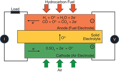
▲ Figure 1. In a solid oxide fuel cell, the cathode reduces oxygen (from air) to O2–, which the electrolyte transports from the cathode to the anode, where it reacts with a fuel to produce H2O, CO2, and electrons.
A solid oxide fuel cell (SOFC) directly converts the chemical energy in fossil fuels into electrical power via an electrochemical reaction. A SOFC (Figure 1) has three basic functional elements: cathode, electrolyte, and anode. The cathode reduces oxygen (in the form of O2) in the air supplied to it into O2–. The electrolyte transports oxygen continuously, in the form of O2–, from the cathode to the anode under a gradient of oxygen chemical potential. At the anode, or fuel supply electrode, the O2– delivered by the electrolyte reacts with hydrogen or a hydrocarbon fuel to produce H2O, CO2, and electrons. The electrons required for the cathode reaction are released by the anode and arrive at the cathode via an external load that produces electricity. The overall driving force for a SOFC is the gradient of oxygen chemical potential that exists between the cathode with a high oxygen partial pressure and the anode with a low oxygen partial pressure. References 1–3 provide a more detailed review of SOFC technology.
Like the components of a battery, each SOFC component exhibits an internal resistance to either electronic or ionic current flow, often expressed as voltage loss. The terminal cell voltage is, therefore, the open circuit voltage (or electromotive force, EMF, if no fuel is lost by any means) reduced by the individual voltage loss of each cell component.
The maximum cell voltage of a typical single SOFC with air as the oxidant is generally 1.2 V, depending on temperature, system pressure, and fuel composition. This voltage is obviously inadequate for any type of practical application. To obtain a sufficiently high voltage and power, multiple single cells are connected in series and/or in parallel by interconnects and/or cell-to-cell connectors that are electronic conductors and oxide-ion insulators.
SOFC stack designs
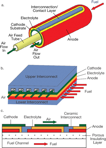
▲ Figure 2. The SOFC substrate supporting the thin electrolyte film can be made into a tubular (a) or planar (b) shape. The segment-in-series design (c) is a special type of planar construction made by depositing multiple cells in series on an electrochemically inactive and electrically insulating substrate. Source: Adapted from (1).
To increase the reliability and reduce the cost of SOFCs, designers strive to obtain high performance at low operating temperatures. To achieve this goal, modern SOFCs typically contain a thin electrolyte film supported on a substrate — a porous or channeled dense layer that enables gas transport. The porous electrode (cathode or anode), dense metal or ceramic interconnect, or porous inactive insulator can serve as the substrate. The substrate can be made into either a tubular or a planar shape (Figure 2).
An important requirement for a SOFC is that oxygen must be transported across the electrolyte in the form of O2–, but not as molecular O2. To achieve this, dense barriers between air and fuel must be established. In the tubular SOFC design, dense electrolyte and interconnect layers create such a barrier, allowing air and fuel to meet only at the open end and combustion to occur only after most of the fuel has been consumed by the oxidation reaction over the entire cylindrical surface. Tubular SOFCs, therefore, do not need a physical sealing material. Planar SOFCs, on the other hand, require sealing materials along the perimeters of the interconnect/electrode and electrolyte/electrode interfaces to prevent air from mixing with fuels, which often presents a challenge to the reliability and stability of the planar SOFCs.
Certain substrate/geometry combinations have advantages. For example, a cathode substrate paired with a tubular stack design is an excellent marriage. Because cell-to-cell connections in the stack take place in a reducing atmosphere, inexpensive transition metals such as nickel and copper can be used. Otherwise, more-expensive noble metals are needed for connecting anode-supported cells into stacks in an oxidizing atmosphere. Figure 2a shows a cathode-supported tubular SOFC stack designed by Siemens/Westinghouse.
On the other hand, an anode substrate and a planar stack is a good combination. High-power-density anode-supported single cells can operate at a lower temperature, allowing economic, commercially available oxidation-resistant alloys to be used to connect single cells into a stack. The oxidation-resistant alloys provide the mechanical support for the stack and function as interconnects and current collectors simultaneously. Figure 2b shows an anode-supported planar SOFC stack designed by FuelCell Energy.
Porous metal substrates have garnered considerable interest in recent years. Potential advantages include robustness and cost-effectiveness of cells and stacks made with these materials. However, a major challenge is the fabrication of dense electrolyte and/or interconnect layers on the substrate at a temperature low enough to prevent significant oxidation and chemical reactions between underlying layers. In addition, vaporization of chromium from the chromium-containing metal interconnects during operation can degrade the cathode performance in the presence of air and moisture.
Multiple cells have also been deposited in series on an electrochemically inactive and electrically insulating substrate. This design, termed segmented-in-series, has unique advantages, including low fabrication costs. More importantly, such a SOFC stack operates at higher voltage and low current for a fixed power rating. This feature could help reduce the power losses on current connections, which is particularly important for large-class SOFC generators. Figure 2c shows a segmented-in-series SOFC designed by LG Fuel Cells.
Advantages of SOFCs
Since a SOFC operates on electrochemical principles, its efficiency is unbounded by the Carnot cycle...
Would you like to access the complete CEP Article?
No problem. You just have to complete the following steps.
You have completed 0 of 2 steps.
-
Log in
You must be logged in to view this content. Log in now.
-
AIChE Membership
You must be an AIChE member to view this article. Join now.
Copyright Permissions
Would you like to reuse content from CEP Magazine? It’s easy to request permission to reuse content. Simply click here to connect instantly to licensing services, where you can choose from a list of options regarding how you would like to reuse the desired content and complete the transaction.