
Before you begin pressure-relief system design, watch out for these common mistakes in identifying overpressure scenarios, performing sizing calculations, and installing the system in the field.
Errors in the design and installation of pressure-relieving devices (PRDs) and their respective pressure-relief systems (PRSs) create risk. For example, incomplete documentation is confusing, creates nuisance rework, and can put a facility at risk of citation. Improper equipment selection and installation can also present real safety hazards.
Inexperienced as well as experienced engineers are bound to make or discover mistakes at some point in their careers. If an error is made in PRS design, we must learn from that mistake and communicate that knowledge. This article will help you recognize common rationale, sizing, and installation pitfalls, and eliminate unnecessary risk at the earliest opportunity.
Begin at the fundamental level
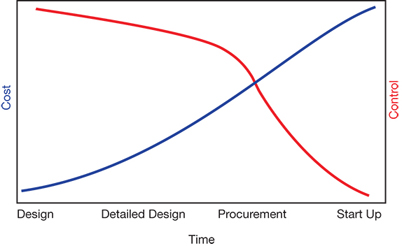
▲ Figure 1. It is easier to control cost, process safety, and other factors at the beginning of the design process than during the end stages of a project.
The saying, “The most effective and efficient mitigation or elimination of risk is achieved at the earliest juncture and at the most fundamental level,” can be applied to practically any discipline and any situation, including process safety and pressure-relief system design. In any project, there is the least amount of risk (e.g., financial, safety, etc.) and the greatest amount of control over change at the onset; the opposite becomes true at the end of a project (Figure 1).
To detect and eliminate design and installation deficiencies, you must understand the physical components within the PRS, as well as the system’s implementation. In other words, understand the big picture. This article first describes the potential pitfalls found at the early stages of the big picture, where we have the most influence over the outcome of a design. It then covers pitfalls found in the later stages of design and post-installation.
Before starting PRS work
Despite notions to the contrary, organizations do not ask engineers to design PRSs to pass the time; the work is purposeful and important to the safe operation of facilities. Just as using a dull knife to cut meat increases risk, asking an unintelligent engineer to design a PRS escalates risk. Stay sharp! Engineers who lack awareness or believe that designing a PRS is busy work will develop risk-prone systems. Engineers and supervisors should ask themselves key questions to identify potential pitfalls and to sharpen their minds if dullness is detected.
The engineer. For the sake of this article, let us assume that the engineer is any individual contributor who performs tasks related to PRS or PRD design. Regardless of whether the engineer is responsible for a single design task or an entire cradle-to-grave design, he or she should ask the following questions before starting work:
- What is the scope of work? The scope of work provides specificity and boundary conditions.
- Why does this facility need this PRS or this PRD? Convincing yourself intellectually of the necessity of the PRS will drive you to be more conscientious while you work.
- Which tasks will I be responsible for? Knowing your role and the roles of others prevents double work and omissions.
- Do I know how to do this work? Prior experience is not always a prerequisite, but you must be able to figure out the steps required to complete a task.
- Who should I go to when I have questions? Even the most experienced engineers need someone else with whom they can discuss ideas and ask questions. Do not be afraid to ask questions — it is how you learn.
- What work aid documents are relevant? Be familiar with the codes, standards, practices, and rules used by your facility or organization to ensure consistent, compliant designs — for example, the ASME pressure vessel code ASME VIII (1) and the American Petroleum Institute standard on depressurizing systems, API 521 (2).
The supervisor. The supervisor is responsible for the management of engineers and their work, but may also act as an individual contributor, performing tasks like those done by the engineer.
In addition to asking the previous questions, the supervisor should also ask these questions before starting work:
- Am I available to answer questions? An overburdened supervisor prevents the free exchange of information within the group; supervisors should delegate responsibilities to preempt bottlenecks.
- Are the right people doing the right tasks? While it’s obvious that a junior engineer should not perform a complex task like a tower reflux failure scenario on the first day, it’s less obvious that your senior process engineer should not be focused on junior-level engineering tasks, such as filling out specification sheets for liquid thermal relief valves.
The organization. It is my experience that some organizations perform PRS design, installation, or maintenance better than others. Some of the better performers share several important characteristics:
- OSHA Voluntary Protection Program (VPP) status(3). A facility obtains VPP status when it goes above and beyond the U.S. Occupational Safety and Health Administration’s (OSHA) minimum requirements. This designation indicates that the facility has a collective interest in safe, compliant operation from upper management down to individual contributors.
- dedicated PRS staff. Having staff dedicated to PRS design, installation, and maintenance helps ensure that institutional knowledge is maintained and that the PRS design and installation are carried out in a consistent manner. An organization where employees are focused on unit operations only, or where employees are not familiar with industry standards like API 521, will not be as effective at maintaining their pressure-relief systems.
- a healthy management of change (MOC) system. A good MOC program actively engages personnel responsible for PRS design.
- strong interdisciplinary teamwork. PRS construction and maintenance necessitate the teamwork of multiple disciplines and crafts, including process engineers, piping designers, pipefitters, inspectors, and other specialists. Many organizations have all of these types of individuals, but if there is not an established communication or teamwork protocol to support cross-functional efforts, it will be difficult to construct or maintain PRSs effectively.
Some facilities that fall outside the scope of OSHA’s process safety management (PSM) regulation (4) should, nevertheless, have an internal equivalent for PSM compliance. Otherwise, they may not have a system in place to show why or where PRSs exist, nor an internal impetus to pay attention to their PRSs.
Of course, these qualities do not guarantee success, nor does their absence doom an organization to failure.
Identify overpressure scenarios
The first step in PRS design is identifying overpressure scenarios and qualifying each scenario with a rationalization. For example: Scenario A applies because a fire will boil the liquid contents of this vessel; Scenario B does not apply because there is no upstream source of pressure that can exceed the design pressure of the protected system.
If you assume that a scenario is applicable when it really is not, your PRD will be designed for a contingency that will never occur. On the other hand, overlooking an applicable scenario can cause risk because the PRD sizing requirements are not realized. The rest of this section covers the latter case and reviews some often-overlooked scenarios.
Blocked outlet and overfilling. A check valve can get stuck shut and not permit flow. Or it might have been installed backwards and open in the wrong direction. Either of these situations can lead to overfilling and overpressure.
Centrifugal pump deadhead pressure should be calculated based on maximum possible suction pressure, not normal upstream pressure. Never calculate deadhead pressure based solely on the pump total dynamic head at zero flow — the suction pressure must be added to the total dynamic head to ensure the relief device is sized correctly.
Centrifugal pumps in hot service may perform much differently during a cold startup — when outlets are more likely to become blocked — than they do under normal operating conditions. Look for pumps that operate at very high temperatures (e.g., 400–700°F), and compare the fluid’s specific gravity (SG) at the operating temperature to its SG at ambient temperature.
The pressure exerted by a pump is directly proportional to the specific gravity of a fluid. For example, let us assume that a pump has a maximum suction pressure of 100 psig under all circumstances, and a maximum total dynamic head of 425 ft. Let us also assume that it pumps fluid that has a hot, operating SG of 0.6 and a cold, ambient SG of 0.8. We can calculate the pump deadhead pressure for the hot and cold conditions:

Total dynamic head can be converted to pressure:

where Δp is pressure in psi, h is pump head in ft, and 2.304 is a unit conversion factor.
Thus, hot and cold deadhead can be calculated:
Hot Deadhead = 100 psig + (425 ft × 0.6/2.304) = 211 psig
Cold Deadhead = 100 psig + (425 ft × 0.8/2.304) = 248 psig
For a system that should not exceed 225 psig, the blocked outlet scenario would not apply under hot operating conditions, but it would apply under cold startup conditions.
Do not mistake a positive-displacement pump or compressor for a dynamic machine like a centrifugal pump or axial compressor. Whereas a blocked dynamic machine may continue running without causing overpressure, blocked outlet scenarios will almost always be applicable to positive-displacement machines, which work by moving a fixed volume of fluid at a given rate. Positive-displacement machines pull fluid into a fixed volume and then push the fluid out without allowing simultaneous ingress or backflow. In a blocked outlet condition, compressible fluids (gases and vapors) will continue to accumulate in the fixed volume of the discharge until so much fluid has accumulated that the pressure eventually exceeds the mechanical limitations of the machine. Incompressible fluids (liquids) are much less forgiving, since there is practically no further compression that the fluid can undergo.
Heat and material imbalance (cooling, reflux failures, etc.). Consider the enthalpy (heat) of streams entering and leaving your protected column system, not just heating and cooling duties. For example, say that some overhead exchangers stop working but have residual cooling duty of 20 MMBtu/hr, and the reboiler has a continuous but reduced duty of 19 MMBtu/hr. You might assume that no relief is necessary because the cooling duty exceeds the heating duty. However, the feed stream may be packed with enthalpy, tipping the scale toward a viable overpressure scenario.
Consider a protected column system located downstream of another column system (e.g., a debutanizer downstream of a depropanizer). In the event of upstream heating failure, lighter upstream components can travel downstream to a lower-pressure system, which may cause accumulation of noncondensables, a blocked vapor outlet, and other upsets. You should explore all of these overpressure scenarios when designing the PRS.
Failure of automatic controls. A control valve may fail in any position. Never assume that a control valve will only fail in the position indicated on a piping and instrumentation diagram (P&ID). Murphy’s Law — anything that can go wrong will go wrong — applies to control valves.
Many flow, pressure, and temperature control valves are globe valves, which provide significantly greater resistance to flow than gate, butterfly, and ball valves. However, not all control valves are globe valves. Because control valve symbols are sometimes ambiguous on P&IDs, engineers might mistake one valve type for another, which might cause them to underestimate scenario severity or miss the scenario applicability altogether.
A gas blowby scenario (i.e., vapor blow-through) generally occurs when an upstream liquid level control valve system fails and a liquid level is lost, allowing high-pressure gas or vapor to flow through the liquid line into a lower-pressure downstream system.
Each of this scenario’s stages should be evaluated: First, check upstream and downstream liquid inventories. Second, size for the liquid overfill that would occur if the upstream liquid inventory were to exceed the empty volume downstream. Next, size for the liquid displacement that would occur if high-pressure gas or vapor were to enter the liquid-packed downstream system (pushing liquid out at the volumetric rate that gas or vapor enters). Then, size for the eventual gas blowby that would occur if all of the liquid were to be displaced. Note that gas blowby would not be prevented if the downstream system is first overfilled with upstream liquid through the faulty level controller — indeed, this would create a liquid relief first, followed by liquid displacement, before finally becoming gas blowby.
Inadvertent valve opening (including reverse flow). Control valve bypasses are typically gate valves. This might not affect the applicability of a particular scenario, but it will affect the scenario’s severity, because gate valves are generally much less restrictive than control valves. Bypass gate valves can allow significantly more high-pressure fluid to pass into a lower-pressure system than its control valve counterpart. In addition to inadvertent opening of the bypass, many designers consider the simultaneous, 100% opening of control valves and their bypasses in the control valve failure scenario, which highlights how severe a bypass failure is compared to the failure of a control valve.
Because checking for an inadvertent valve opening in manifolds or tank farms is a tedious task, an engineer can easily miss a scenario simply because of mental fatigue. Consider approaching these scenarios by identifying sources of overpressure first, not valves that can be opened.
Check valves are often overlooked as sources of reverse flow because many engineers assume that they do not fail open (i.e., get stuck open) or leak when they are in the closed position. However, both of these situations do occur, and API Standard 521 (2) encourages engineers to consider this scenario. Check valve failure can go unnoticed during normal operation, which is also known as latent failure.
Chemical reaction. When identifying overpressure scenarios, consider all possible chemical reactions. If you or your supervisor does not have the experience or resources required to perform reactive system relief sizing, seek outside help. Never ignore reactive chemistry.
Fire. Consider the potential for a nearby fire to cause an overpressure in the vessel or tank of interest. Check the distance to possible sources of fire and determine the thermal radiation the fire could produce.
Fluids with high vapor pressures may vaporize rapidly at atmospheric pressure instead of pooling on the ground. If these fluids leak through broken fittings, flanges, or holes, they can create jet fires. There is a common belief that relief valves cannot protect against jet fires because jet fires are very narrowly focused and cause only localized heating with rapid vessel wall failure. However, this is a worst-case scenario; jet fires may dissipate heat across a large surface area, which can cause an overpressure scenario in the impinged vessel. Guidance and formulas in API 521 (2) can help you calculate the heat input for such a scenario.
Adding a PRD to a vessel that may be impinged by a jet fire can allow for depressurizing before a catastrophic vessel failure.
Heat exchanger failure. Always check the maximum allowable working pressure (MAWP) of other equipment and piping connected to a heat exchanger. In the event of a tube leak or rupture in a heat exchanger, the high-pressure side may not cause overpressure of the low-pressure side of the exchanger. However, the piping and equipment connected to the low-pressure side of the exchanger may be susceptible to overpressure.
Pressure-relief device sizing
Once you identify a possible overpressure scenario, you must choose an appropriately sized PRD. Whereas the common pitfalls in overpressure scenario identification are conceptual and easy to overlook, it is easier to prevent and identify mistakes in PRD sizing due to its quantitative nature.
API vs. ASME sizing. Generally, pressure-relief valves are sized using the equations provided in API 520 Part 1 (5), which take slightly different forms depending on the fluid phase being relieved.
To determine the relief area for sonic vapor or gas flow:

where A is relief area, W is flowrate, C is a function of the ratio of ideal gas specific heats (Cpand Cv), Kd is the API effective coefficient of discharge, P1 is the upstream relieving pressure, Kb is the capacity correction factor for backpressure, Kc is the combination correction factor for installations with a rupture disk upstream of a pressure-relief valve (PRV), T is the relieving temperature of the vapor or gas, Z is the compressibility factor for the vapor or gas, and M is the molecular weight of the vapor or gas.
To determine the relief area for liquid flow:
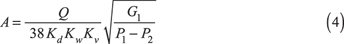
where Q is the volumetric flowrate, Kw is the capacity correction factor for backpressure, Kv is the viscosity correction factor, G1 is the liquid specific gravity at the relieving temperature, and P2 is the total backpressure.
To determine the relief area for two-phase flow:
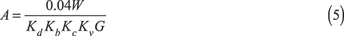
where G is the mass flux.
All of these sizing equations can be reduced to a generic proportionality form:

where K is the discharge coefficient. Any consistent set of units can be used in the proportionality form.
Preliminary sizing can utilize API-designated effective orifice areas and effective discharge coefficient (Kd). But, API 520 Part 1 encourages final sizing and selection using actual area and rated discharge coefficient, which can often be obtained from Ref. 6 (known as the ASME Redbook NB-18).
When sizing a relief valve, never mix ASME values with API values. Mixing these values in calculations can cause you to overestimate the capacity of the PRD, which could lead to vessel rupture during an overpressure event (Table 1).
| Table 1. Mixing API and ASME values can overestimate the capacity of a pressure-relief device. These values are for a 2 ″×J×3″ pressure-safety valve. | ||
| Effective AAPI = 1.287 in2 (per API Standard 526 (7)) Effective Gas Kd = 0.975 | Actual AASME = 1.496 in2 (per NB-18) Rated Gas KASME = 0.86 (per NB-18) | |
| Trial | A × K ∝ W | Note |
| API Values | 1.287 × 0.975 = 1.2555 | Conservative flow capacity estimate |
| ASME Values | 1.496 × 0.86 = 1.2866 | Rated flow capacity |
| AAPI and Gas KASME | 1.287 × 0.86 = 1.1068 | Capacity underestimated by 14% |
| AASME and Gas Kd | 1.496 × 0.975 = 1.4586 | Capacity overestimated by 13%! |
Assume a pressure-safety valve (PSV) has a 2-in. inlet connection, an API J orifice, and a 3-in. outlet connection; this is referred to as a 2″×J×3″ PSV. Many PSVs use this designation to convey relative size (e.g., 3″×K×4″, 8″×T×10″). Table 1 shows that the highest risk occurs when the actual orifice area (AASME) is used with the API gas discharge coefficient (Kd), because the capacity of the PRD would be overstated — i.e., the PRD would be undersized. An undersized PRD will not relieve as much as it should, which can permit overpressure beyond the equipment’s allowable accumulated pressure and lead to a loss of containment.
These types of mix-ups occur more frequently when a PSV is not a standard valve; for example, a full-bore valve or other non-API-letter-designated valve. Avoid the temptation to use the actual area reported by the manufacturer with the Kdvalue specified in API 520 during preliminary sizing.
Mix-ups in liquid sizing may present less risk because liquid KASME values tend to be higher than API liquid Kd, but mix-ups should, nonetheless, be avoided.
Liquid scenario sizing pitfalls
Prior to the 1980s, there was no differentiation between liquid-trim and vapor-trim valves used in relief service — most valves were designed for vapor. Liquid scenarios typically could not drive a vapor-trim valve fully open until approximately 25% overpressure was reached. After 1986, liquid-trim valves were certified to fully open at 10% overpressure.
There is a common misconception that conventional or bellows valves are trimmed to handle both vapor and liquid (i.e., dual-trim). Do not assume that a vapor-trim valve can relieve liquid just as well as a liquid-trim equivalent. Only some valves have this dual-trim characteristic; the most widely used is the modulating pilot relief valve. Conventional and balanced bellows valves with dual-trim are exceedingly rare.
If a valve has a vapor trim (i.e., is not certified for liquid), its capacity for liquid scenarios must be de-rated using the Kp factor, which is 0.6 for 10% overpressure scenarios. Otherwise, the capacity can be overestimated by 66% or more!
Vapor scenario sizing pitfalls
Liquid-trim valves have geometry that allows them to open properly for liquid overpressure scenarios. Although liquid-trim valves will also open for vapor scenarios, the gas coefficient of discharge for a liquid-trim valve will not be identical to that of a similar vapor-trim valve. There is no published consensus for a gas coefficient of discharge corrected for liquid-trim valves, but there is ongoing discussion within AIChE’s Design Institute for Emergency Relief Systems (DIERS), as well as in the API Subcommittee on Pressure-Relieving Systems (SCPRS).
It is widely believed and accepted that conventional or bellows valves with liquid trim will have the same gas coefficient of discharge as a similar vapor-trim valve, but that is not necessarily true. The gas coefficient of discharge in a liquid-trim valve will be de-rated from its vapor-trim equivalent (i.e., the Kd would be less than 0.975 for vapor flowing through a liquid-trim valve).
Keep an eye out for liquid-trimmed valves at or near their capacity for vapor scenarios and recognize that capacity may be overestimated in these situations.
Compressibility factor
PRDs for fluids with a compressibility factor (Z) outside of the range of 0.8–1.1 should be sized using the direct integration approach described in Annex B of API 520 Part 1 (5), because the standard method of vapor sizing for critical flow is not always appropriate at these conditions. Whereas the standard vapor sizing equations consider compressibility at the PRD inlet pressure only, the direct integration approach follows the fluid behavior (i.e., density) along an isentropic expansion path as it depressurizes through the PRD nozzle from the inlet pressure to the downstream pressure. The latter approach can provide a more accurate prediction of fluid behavior, and thus the flow, through the PRD.
Most contemporary software will guide users to the applicable equations if fluid compressibility is outside the prescribed range. Older installations may have been sized using the incorrect method or formulas. Often, the incorrect sizing formulas are applied when designers use simpler sizing tools such as back-of-napkin calculations and Excel spreadsheets.
This pitfall is not as common for installations sized or revalidated within the past ten years. Be aware that smaller or older facilities with many high-pressure gas and vapor services are more likely to have used traditional vapor sizing rather than direct integration, so overestimation of valve capacity is likely only a problem where installed devices are at or near their capacities.
Two-phase scenario sizing: Subcooled inlet, flashing outlet
Choosing a fluid’s correct initial relief temperature is important because it can significantly influence subsequent flashing. A process fluid may be subcooled at the inlet of the relief device and then begin flashing as it depressurizes through the PRD and into the disposal system (or atmosphere).
For example, assume that a pressurized vessel contains saturated water normally at 300°F (52 psig operating pressure) and has a PRD discharging to atmosphere set at 100 psig. However, the same vessel may operate as high as 326°F (83 psig). If liquid overfilling is a valid overpressure scenario, the engineer might be tempted to size the PRD using the normal operating temperature (300°F). As the liquid water exits the PRD and enters the atmosphere, it will flash because the boiling point at atmospheric pressure is approximately 212°F. The amount of flashing, though, is influenced by the initial temperature. In fact, the amount of flashing (the volume of liquid that expands into a vapor) will be greater if the initial relief temperature is 326°F. Since the volumetric flow and PRD sizing requirements are larger when there is more flashing, it is wise to choose the higher, albeit abnormal, temperature.
Detailed design
The step between sizing and installing a PRD is the detailed design phase, during which the rest of the PRS design is developed. Engineers are not typically responsible for the detailed design of new PRS installations. For example, an engineer may specify that the PRD outlet needs to be 6-in. Sch. 40 piping, but may not determine the precise geometry of the disposal system.
Two pitfalls commonly prevent engineers (and organizations) from successfully bridging the gap between PRD sizing and proper installation — pockets and unintended pipe dimensions.
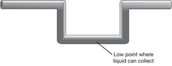
▲ Figure 2. Liquid can accumulate in a pocket, i.e., a low point in horizontal piping, which will limit relief capacity.
Pockets. A pocket is a low point in a piping system (Figure 2), which can limit relief capacity, block flow, incite damaging slug flow, and allow liquids to accumulate.
Process engineers often scribble “DO NOT POCKET” on P&IDs that they send to pipe designers for detailed design, but sometimes the installation ends up with pockets nonetheless. There are many convenient excuses for putting pockets in PRD outlet piping (e.g., running piping to go around existing structures), but the real culprit is often a lack of communication. Engineers must be sure to communicate and work with pipe designers to avoid pockets. Pipe designers will do their best to follow guidance from engineers on design P&IDs, but they may not know where to turn if something is in the way of the engineer’s pocketless vision.
Unintended pipe dimensions and tie-ins. Shorter pipe lengths with larger diameters are often desirable in relief device installations because they have smaller pressure drops than longer, smaller-diameter piping. The engineers designing PRDs often do not work in the facility where the PRD will be installed and may not know where platforms, catwalks, or other piping and valves are located. Thus, the routing for new PRS piping is often determined only after someone walks through the facility to identify the physical locations and limitations. Although the engineer may have envisioned a PRS with 5-ft inlet and 40-ft outlet piping, in reality the detailed design may need to be much longer with many more fittings, which adversely affects the pressure drop and desired tie-in location. If this occurs, the engineer must adjust the sizing calculations to account for the longer piping, because the pressure drop might increase and the relief capacity decrease.
The key to preventing this pitfall, too, is to communicate with the pipe designers! The importance of dialogue during detailed design is often overlooked, but can be critical if pressure drop becomes too high.
Spotting bad installations on P&IDs
Once equipment is designed, purchased, and installed, it becomes as-built. The term as-built simply refers to how equipment exists in the field and how its installation is depicted in engineering drawings. Sometimes, designs that seem good on paper are installed poorly in the field.
Reviewing how a PRS is depicted on as-built P&IDs can reveal troubled installations.
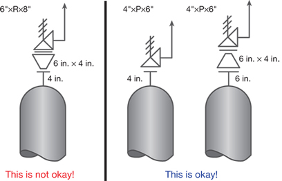
▲ Figure 3. PRD inlets must not be larger than the connection to the protected equipment.
Expanders in PSV inlet piping. A PRD’s inlet should be smaller than or the same size as the connection on the equipment that the PRD protects (Figure 3). This is an ASME VIII code requirement, and violation of it carries the risk of an OSHA citation. Expanders in the PRD’s inlet piping can limit PRD capacity and cause increased inlet pressure drop.
Relief device set pressure higher than protected equipment set pressure. With a few specific exceptions, the PRD set pressure must always be specified at or below the equipment’s MAWP. If the PRD set pressure is higher than the MAWP on a P&ID, it is typically a typographical error. But if this is the as-built condition, it represents a higher risk of loss of containment, since PRDs are designed to protect at 10%, 16%, or 21% pressure accumulation as per ASME VIII guidelines (1). This concern is more likely to occur when the MAWP of a piece of equipment is de-rated or an MOC system does not actively engage PRS personnel.
Relief device installed on the bottom of a liquid system. Ideally, PSVs should be installed in the vapor space of equipment. PRDs installed in the liquid space are much more susceptible to liquid displacement or two-phase flow, which may have been overlooked in the evaluation of vapor scenarios (e.g., fire). This installation concern carries the physical risk of inadequate sizing to handle liquid displacement or two-phase flow conditions.
Check valves in the relief device outlet piping. Check valves cannot be guaranteed to remain open, nor can they be controlled open by administrative means. The potential blockage of a check valve carries the physical risk of the relief device failing to handle overpressure. For this reason, check valves should not be located in the relief path.
Spotting bad installations in the field
For any installation concern that can be spotted on a P&ID, subsequent visual confirmation in the field is warranted. In addition to the pitfalls you can find on P&IDs, visual verification can also reveal:
Lengthy inlet piping. Lengthy or tortuous inlet or outlet piping may incur significant pressure drop. Although a relief design basis that does not reflect the as-built piping situation may pose a citation risk, inordinate pressure drop may cause relief device instability and backpressure-limited capacity, which pose physical risks. These concerns are most pronounced in large relief devices (e.g., 4″×P×6″, 6″×Q×8″, 6″×R×8″, 8″×T×10″).
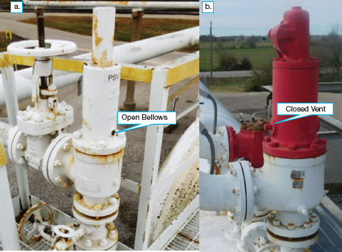
▲ Figure 4. (a) Bellows vents must not be blocked or closed. (b) A closed bellows vent will have little to no relief capacity when backpressure exceeds overpressure.
Plugged bellows vent. Some PSVs are balanced against the effect of back-pressure by a bellows, which is vented from the PSV to atmosphere. Bellows vents are often labeled DO NOT BLOCK, but mistakes happen (Figure 4). Blocking the bellows vent turns the balanced PSV into a conventional, unbalanced PSV, which presents the physical risk of having little to no relief capacity when back-pressure exceeds overpressure.
Intervening gate valves installed with stems pointing up. Gate valves allow for isolation of relief devices for maintenance purposes and are sealed open during normal operation. Long-term corrosion or vibration can break or shake gates loose from their stems, which may go unnoticed; if a gate valve in horizontal piping is installed with its stem pointed up, a dislodged gate could block the relief path entirely. Therefore, it’s crucial that these valves are installed on their sides.
Sideways relief valves. PSVs should be installed in the vertical upright position. Sideways valves may not operate as intended — either opening unexpectedly or leaking.
Atmospheric outlet piping within arm’s reach. Relief devices discharging to atmosphere should vent to a safe location. If you can look into the end of a PRD tailpipe, DON’T. This PRD and discharge piping has been installed incorrectly.
Closing thoughts
If you find that you have made any of the PRS design and installation mistakes described in this article, it is important to:
- own the mistake
- generate preliminary solutions
- communicate the mistake
- correct the mistake with finalized solutions
- learn from experience and do not make the same mistake again.
This is easier said than done, but good engineers are duty-bound to own and communicate their mistakes so that they are not repeated.
Nomenclature
A = relief area
C = a function of the ratio of ideal gas specific heats
Cp = ideal gas specific heat for constant pressure
Cv = ideal gas specific heat for constant volume
G = mass flux
G1 = liquid specific gravity at the relieving temperature
h = pump head
K = discharge coefficient
Kb = capacity correction factor for backpressure
Kc = combination correction factor for installations with a rupture disk upstream of a pressure-relief valve
Kd = API effective coefficient of discharge
Kv = viscosity correction factor
Kw = capacity correction factor for backpressure
M = molecular weight of the vapor or gas
P1 = upstream relieving pressure
P2 = total backpressure
Q = volumetric flowrate
SG = specific gravity
T = relieving temperature of the vapor or gas
W = flowrate
Z = compressibility factor of the vapor or gas
Greek Letters
Δp = change in pressure
Literature Cited
- American Society of Mechanical Engineers, “Rules for Construction of Pressure Vessels,” BPVC Section VIII Div. 1, New York, NY (2015).
- American Petroleum Institute, “Pressure-Relieving and Depressuring Systems,” Standard 521, 6th ed., API, Washington, DC (Jan. 2014).
- U.S. Occupational Safety & Health Administration, “Voluntary Protection Programs,” Directorate of Cooperative and State Programs, OSHA, U.S. Dept. of Labor, Washington, DC, www.osha.gov/dcsp/vpp/index.html (accessed Feb. 2016).
- U.S. Occupational Safety & Health Administration, “Process Safety Management of Highly Hazardous Chemicals,” 29 CFR 1910.119, U.S. Dept. of Labor, Washington, DC, www.osha.gov/pls/oshaweb/owadisp.show_document?p_table=STANDARDS&p_id=9760 (accessed Feb. 2016).
- American Petroleum Institute, “Sizing, Selection, and Installation of Pressure-Relieving Devices, Part I — Sizing and Selection,” Standard 520, Part I, 9th ed., API, Washington, DC (July 2014).
- National Board of Pressure Vessel Inspectors, “National Board Pressure Relief Device Certifications,” NB-18, Columbus, OH, www.nationalboard.org/Index.aspx?pageID=64 (accessed Feb. 2016).
- American Petroleum Institute, “Flanged Steel Pressure-Relief Valves,” Standard 526, 6th ed., API, Washington, DC (May 2009).
Learn more with AIChE Webinars
This article is based on the AIChE webinar, “Whoops! I Made a Mistake Sizing My Relief Device and Then I Installed It Incorrectly!” To watch this webinar, as well as other webinars presented by Justin Phillips, P.E., visit www.aiche.org/academy.
1

Copyright Permissions
Would you like to reuse content from CEP Magazine? It’s easy to request permission to reuse content. Simply click here to connect instantly to licensing services, where you can choose from a list of options regarding how you would like to reuse the desired content and complete the transaction.